
Method for removing electroplated metal facets and reusing a barrier layer without chemical mechanical polishing

a technology of electroplating metal facets and barrier layers, which is applied in the direction of semiconductor devices, semiconductor/solid-state device details, electrical apparatus, etc., can solve the problems of patents that do not appear to address the removal of copper facets, suggest barrier layer reuse, and cannot significantly reduce the cost of the total process that includes a cmp step. , to achieve the effect of reducing the threshold of tsv technology industrialization and the cost of manufacture, reducing the cost of tsv

Active Publication Date: 2015-03-12
NAT CENT FOR ADVANCED PACKAGING
View PDF1 Cites 6 Cited by
  • Summary
  • Abstract
  • Description
  • Claims
  • Application Information

AI Technical Summary

Benefits of technology

This patent describes a method for producing a smooth and level surface by removing electroplated copper facets and reusing the barrier layer. This method allows for the reuse of the barrier layer, decreasing the integration process cost and lowering the threshold of TSV technology industrialization and the cost of manufacture.

Problems solved by technology

Due to the high cost of CMP equipment and slurry consumption, one cannot significantly decreasing the cost of the total process that includes a CMP step.
But the patent does not appear to address removing copper facets formed by electroplating, and does not suggest barrier layer reuse.
An appreciable obstacle to the removal of overburden copper facets is the difficulty of smoothing and deburring the metal layer surface in semiconductor manufacturing in recent years.
This is due to the difficulty in volatilizing the compound formed during inductively coupled plasma (“ICP”) etching processes.
CMP of such surfaces is rather expensive and may produce stress in the surface structure of the wafer, which can have an adverse effect on the corrosion resistance of the wafer.
Accordingly, the CMP produces waste and may be harmful to the environment.

Method used


Image

  • Method for removing electroplated metal facets and reusing a barrier layer without chemical mechanical polishing
  • Method for removing electroplated metal facets and reusing a barrier layer without chemical mechanical polishing
  • Method for removing electroplated metal facets and reusing a barrier layer without chemical mechanical polishing

Examples


Embodiment Construction

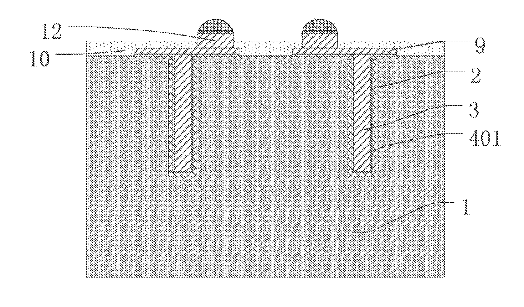
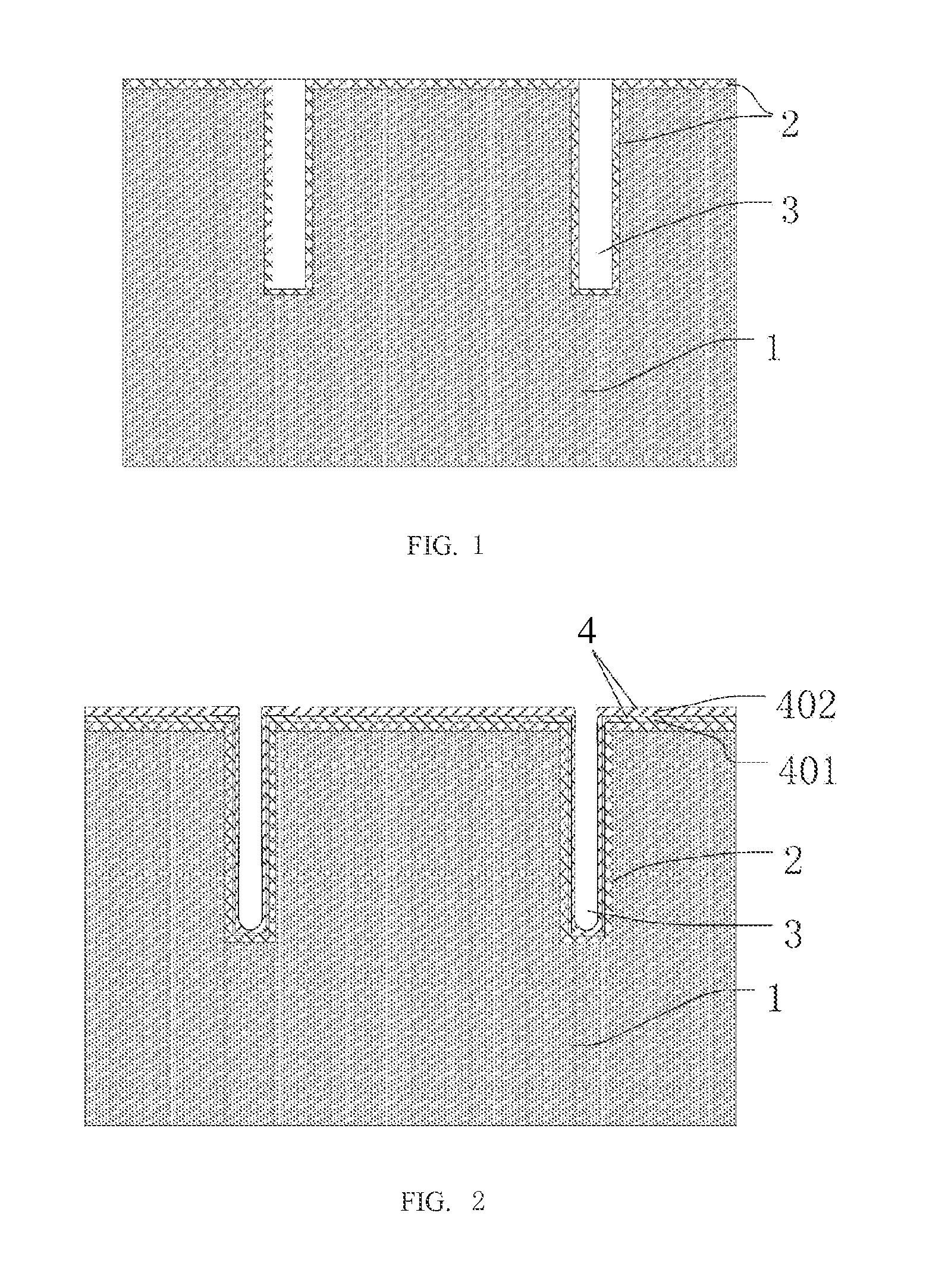
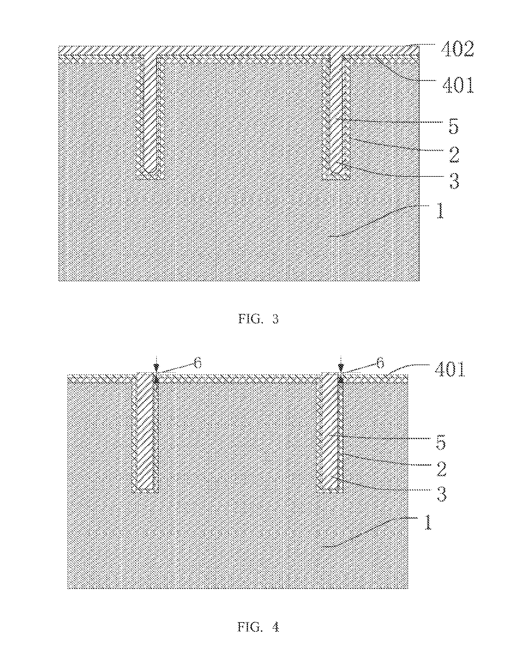
[0030]An exemplary method in accordance with an embodiment of the invention for removing electroplated metal, e.g., copper, facets and reusing the barrier layer includes the following steps.

[0031]As used herein, a through-silicon via is an electrical connection extending through a silicon or other semiconductor wafer or through a die.

[0032]Referring to FIG. 1, in step S1, a substrate, such as a silicon wafer 1, is provided. A blind via i.e., a via such as a TSV, is defined in the wafer. The blind via depth and diameter are set according to specific requirement. The blind via with the vertical sidewall may be defined by, e.g., deep reactive-ion etching (“DRIE”) or laser drilling. Generally the ratio of depth to diameter is at least 3:1.

[0033]Thereafter, an insulation layer 2 is deposited on the wafer 1, lining the blind via. The insulation layer may include, for example, silicon dioxide, silicon nitride, silicon oxynitride, an organic polymer , et cetera. The insulation layer may inc...


PUM


Abstract

A method for avoiding using CMP for eliminating electroplated copper facets and reusing barrier layer in the back end of line (“BEOL”) manufacturing processes. Electropolishing is employed to remove the deposited surface metal, stopping at the barrier layer to form a smooth surface that may be utilized in subsequent steps. The method is suitable for the electropolishing of metal surfaces after formation of filled vias for through-silicon via processes employing metals such as copper, tungsten, aluminum, or alloys thereof. The remaining barrier layer may be reused to fabricate the redistribution layer.

Description

PRIOR APPLICATION[0001]This application claims priority to CN 201310412558.6, filed Sep. 11, 2013, the entire contents of which are incorporated by reference herein.FIELD OF THE INVENTION[0002]Embodiments of the invention relate generally to semiconductor device packaging technology, particularly to a process of removing electroplated metal facets, such as copper facets.BACKGROUND OF THE INVENTION[0003]Many different electropolishing processes may be used for the processing of various metals and its alloy. The purpose of the process of electrochemical polishing or electropolishing is to produce metal surfaces of high purity, and to smooth and deburr the metal surfaces. Smoothing in the micro range can also produce gloss in the treated wafer surfaces. Furthermore, electropolishing can also remove any stresses from the outer layers of the metal layers.[0004]The electroplating deposition (“ECD”) of copper is the main technology for through-silicon via (“TSV”) filling in advanced packag...

Claims


Application Information

Patent Timeline
IPC IPC(8): H01L21/768H01L23/00
CPCH01L21/76898H01L24/11H01L21/76865H01L21/76846H01L21/32115H01L21/32125H01L21/7684H01L21/76841H01L24/03H01L24/05H01L24/13H01L2224/02372H01L2224/02377H01L2224/03462H01L2224/0391H01L2224/03914H01L2224/0401H01L2224/05548H01L2224/05567H01L2224/05647H01L2224/1134H01L2224/13022H01L2224/13024H01L2924/00014H01L2924/12042
Inventor XUE, KAIYU, DAQUAN
Owner NAT CENT FOR ADVANCED PACKAGING
Learn More