Differential signal transmission cable
a transmission cable and signal technology, applied in the direction of power cables, cables, insulated conductors, etc., can solve the problems of variable distance from each signal conductor, and achieve the effect of reliably supporting high-speed transmission signals, reducing the difference in the effective dielectric constant between the signal conductors, and reducing the occurrence of skews
- Summary
- Abstract
- Description
- Claims
- Application Information
AI Technical Summary
Benefits of technology
Problems solved by technology
Method used
Image
Examples
first embodiment
[0033]the present invention will now be described in detail with reference to the drawings.
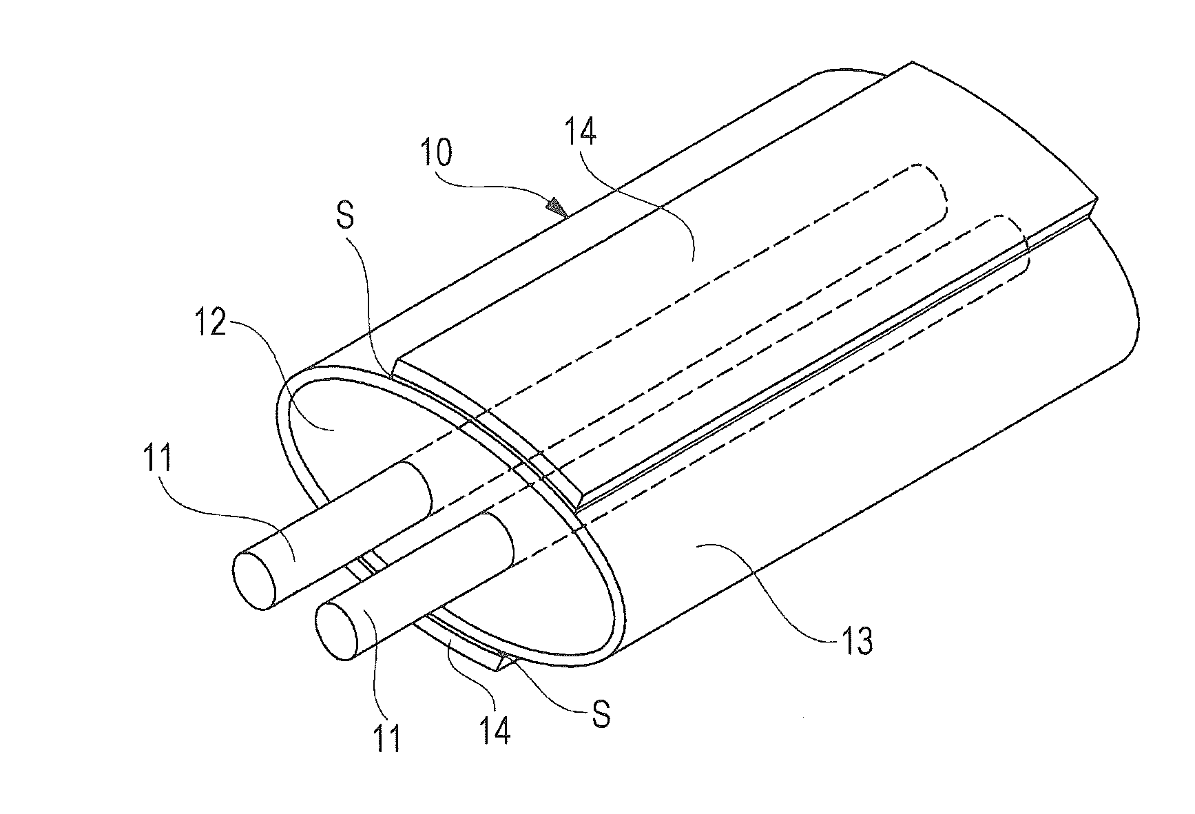
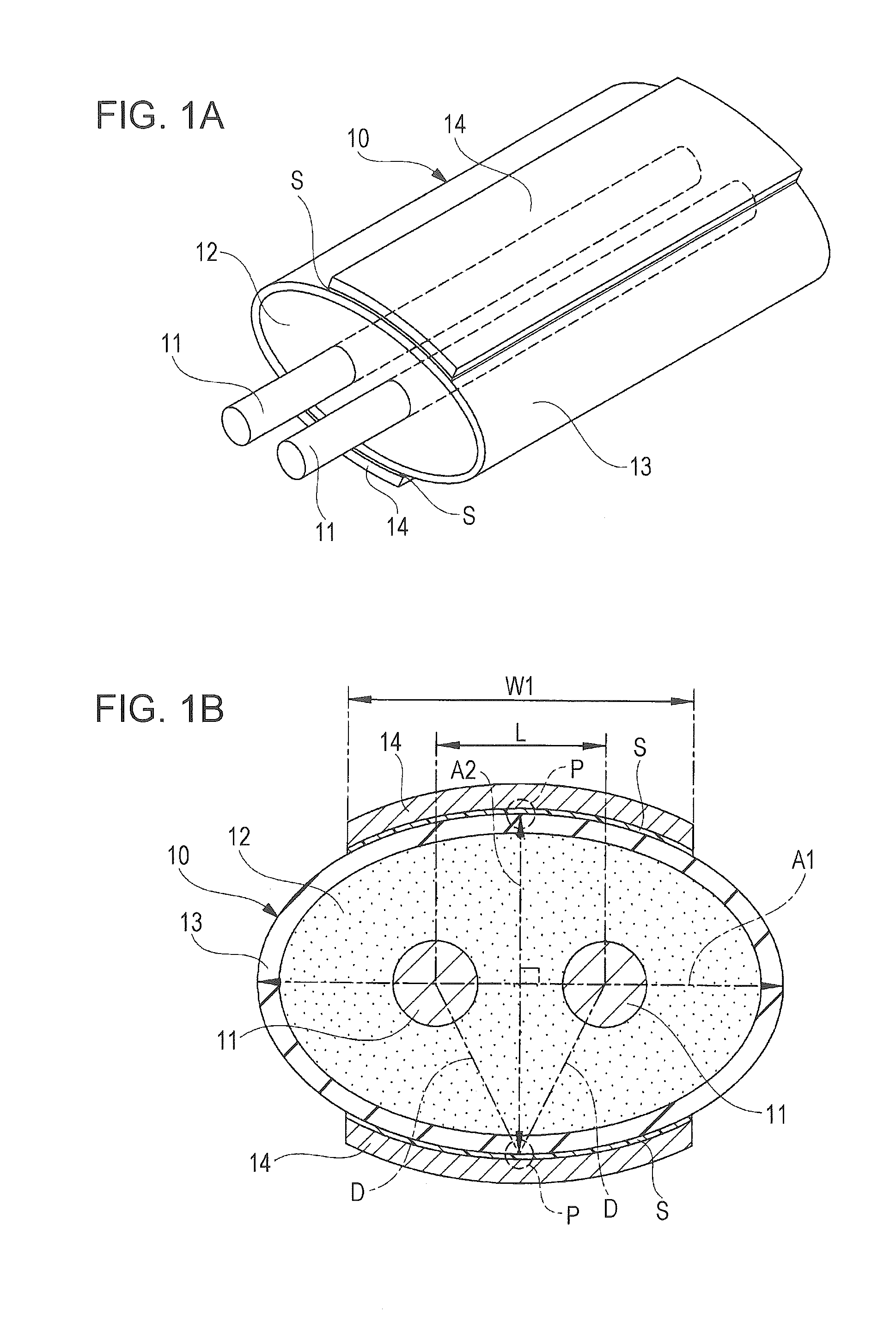
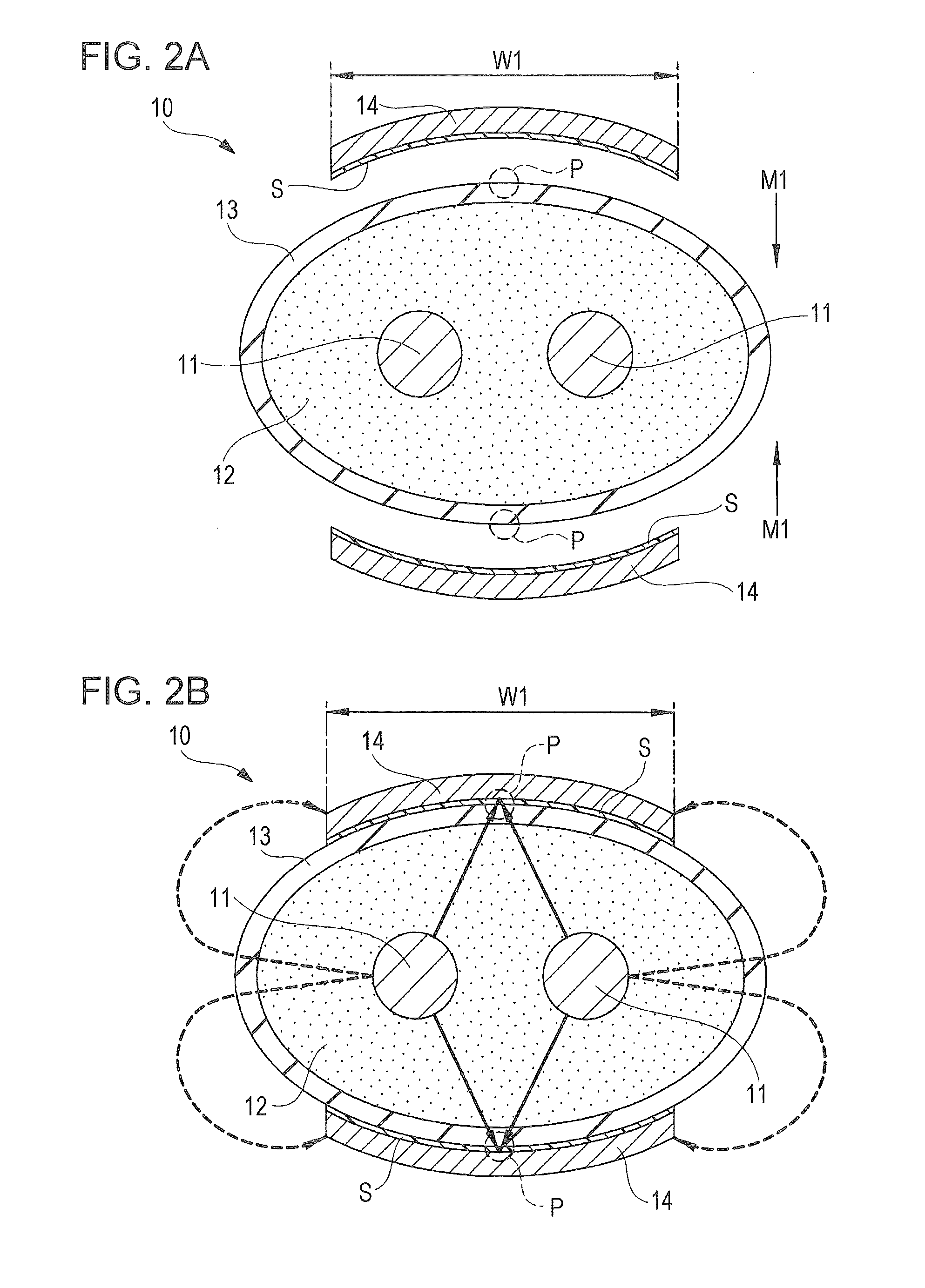
[0034]FIG. 1A is a perspective view of a differential signal transmission cable according to the first embodiment, and FIG. 1B is a transverse cross-sectional view of FIG. 1A. FIG. 2A is a transverse cross-sectional view illustrating how shield conductors are attached, and FIG. 2B is a transverse cross-sectional view schematically illustrating an electric field emanating from each signal conductor to the shield conductors.
[0035]As illustrated in FIGS. 1A and 1B, a differential signal transmission cable 10 of the first embodiment includes a pair of signal conductors 11. A plus-side signal (positive: +) serving as a differential signal is transmitted through one of the signal conductors 11, and a minus-side signal (negative: −) serving as the other differential signal is transmitted through the other of the signal conductors 11. Each signal conductor 11 is formed, for example, by a silver-plated...
second embodiment
[0052]FIG. 3A is a transverse cross-sectional view of a differential signal transmission cable and FIG. 3B is a transverse cross-sectional view illustrating how shield conductors in FIG. 3A are mounted.
[0053]As illustrated in FIG. 3A, in a differential signal transmission cable 20 of the second embodiment, each shield conductor 22 is secured to the surface of the skin layer 13, with polyester tape (hereinafter, PET tape) 21 serving as an insulator and adhesive sheet. That is, the PET tape 21 is interposed between the skin layer 13 and each shield conductor 22. The shield conductor 22 is secured to the PET tape 21 in advance. This facilitates positioning of each shield conductor 22 with respect to the skin layer 13. That is, when the PET tape 21 having a larger surface area than the shield conductor 22 is positioned with respect to the skin layer 13 and attached thereto as indicated by arrows M2 in FIG. 3B, the shield conductor 22 automatically covers the equidistant portion P. In t...
third embodiment
[0056]FIG. 4A is a transverse cross-sectional view of a differential signal transmission cable and FIG. 4B is a transverse cross-sectional view illustrating how shield conductors in FIG. 4A are mounted.
[0057]Unlike the differential signal transmission cable 10 of the first embodiment, a differential signal transmission cable 30 of the third embodiment illustrated in FIGS. 4A and 4B has no skin layer 13 (see FIGS. 1A and 1B) and has an insulating member (insulator) 31 made of solid polyethylene containing no air bubbles. A pair of shield conductors 32 is secured by winding a sheet of PET tape 33, which serves as an insulator and adhesive sheet, around the insulating member 31 and attaching the PET tape 33 to the insulating member 31. That is, the PET tape 33 is interposed between the insulating member 31 and each shield conductor 32. The shield conductors 32, spaced apart by a predetermined distance, are secured to the PET tape 33 in advance. With one shield conductor 32 (on the low...
PUM
| Property | Measurement | Unit |
|---|---|---|
| dielectric constant ∈ef | aaaaa | aaaaa |
| shape | aaaaa | aaaaa |
| width dimension | aaaaa | aaaaa |
Abstract
Description
Claims
Application Information
 - R&D
- Intellectual Property
- Life Sciences
- Materials
- Tech Scout
- Unparalleled Data Quality
- Higher Quality Content
- 60% Fewer Hallucinations
Browse by: Latest US Patents, China's latest patents, Technical Efficacy Thesaurus, Application Domain, Technology Topic, Popular Technical Reports.
© 2025 PatSnap. All rights reserved.Legal|Privacy policy|Modern Slavery Act Transparency Statement|Sitemap|About US| Contact US: help@patsnap.com


