Apparatus And Method For Igniting A Gaseous Fuel In A Direct Injection Internal Combustion Engine

Active Publication Date: 2015-01-22
WESTPORT FUEL SYST CANADA INC
View PDF4 Cites 36 Cited by
  • Summary
  • Abstract
  • Description
  • Claims
  • Application Information

AI Technical Summary

Benefits of technology

The patent describes an improved method and apparatus for igniting gaseous fuel in an internal combustion engine. The method involves heating a space near a fuel injector with a pilot amount of gas, introducing a main amount of gas during a second stage injection event after the pilot has ignited, and using the heat from the pilot to ignite the main amount of gas. The pilot can be introduced through multiple pilot injection passages, and the main amount of gas can be introduced through a main injection passageway. The apparatus includes a fuel injector with a pilot injection passageway and a main injection passageway, a heat source for heating the space near the fuel injector, and a controller for actuating the fuel injector. The method and apparatus can improve ignition and combustion in the engine, and can also improve the performance and reliability of the engine.

Problems solved by technology

Engines in which natural gas is directly injected into combustion chambers have achieved limited commercial success in the trucking industry.
Considering also the lower cost of natural gas compared to diesel, the adoption of natural gas in the trucking industry has seen steady but limited growth.
This solution although effective and employed extensively in the heavy duty trucking industry adds cost and complexity to the engine that now needs to support two fuel systems, which reduces overall fuel system reliability.
In this manner it is difficult to control the heat release rate.
As a result, the flame produced may not propagate sufficiently to burn all the fuel due to inadequate mixing.
Such systems suffer from high unburned hydrocarbon (UHC) emissions and have high cycle-to-cycle variability, which makes it difficult to meet ever more stringent emission regulations.
Glow plugs have several failure modes which are generally related to effects from operating temperature and inconsistent combustion.
For example, too much electrical power delivered to the glow plug from the engine battery causes excessive heating leading to elevated temperatures beyond what the glow plug is capable of providing.
Driving circuit failure can lead to this power overload condition.
Poor fuel injection timing, that is fuel injected too early or too late, leads to poor combustion performance which causes carbon deposit build-up on the glow plug surface.
General fouling of the glow plug occurs when contaminants in the fuel supply are not properly filtered and are let into the combustion chamber.
Both carbon deposit and contaminant build-up phenomena further worsen combustion performance since the heat delivered to the fuel is retarded by the build-up.
These failure modes can affect glow plug performance prior to failure which can contribute to even greater emission levels.
Glow plugs operate at very high temperatures, for example at 1,350° C., which in general reduces the operating life due to heat fatigue.
The shortcomings of conventional techniques for igniting gaseous fuels in Diesel-cycle engines have limited the market adoption of using these fuels in place of diesel.

Method used


Image

  • Apparatus And Method For Igniting A Gaseous Fuel In A Direct Injection Internal Combustion Engine
  • Apparatus And Method For Igniting A Gaseous Fuel In A Direct Injection Internal Combustion Engine
  • Apparatus And Method For Igniting A Gaseous Fuel In A Direct Injection Internal Combustion Engine

Examples


second embodiment

[0086]Referring now to the schematic view of FIG. 6, there is shown a second embodiment which is similar to the previous embodiment and like parts have like reference numerals and are not described in detail, if at all. Ignition source 130 includes diverting and retaining member 540 that extends partially around an outer periphery of ignition source 130 on either side of orifice 470. When valve body 300 comprises multiple pilot injection orifices 470, then each such orifice 470 has a respective diverting and retaining member 540. During injection of the pilot fuel through passageway 460, pilot jet 520 impacts diverting member 540 which diverts the flow around the perimeter of valve body 300 in both directions increasing residence time by retaining pilot fuel near heated surface 510. The impact causes turbulence in jet 520 which improves mixing of pilot fuel without it becoming overly lean. Since residence time is increased by member 540, the pilot fuel has more time to heat to its a...

third embodiment

[0087]Referring now to the schematic view of FIG. 7, there is shown a third embodiment which is similar to the previous embodiments and like parts have like reference numerals and are not described in detail, if at all. Sparking mechanism 545 ignites gaseous fuel by spark ignition and comprises spark ring 550 and source electrodes 560. Spark ring 550 is a ground electrode and extends around a perimeter of valve body 300 and is secured to ignition source by post 570. Source electrodes 560 are spaced along the path of ring 550 and are a source of electrical energy for which ring 550 is a return path to ground for sparks that occur when a sufficient voltage differential exists between electrodes 560 and ring 550. In a preferred embodiment there is at least one electrode between respective pairs of pilot injection orifices 470 around valve body 300, for which only one such passageway is shown in FIG. 7, although this is not a requirement. During injection of the pilot fuel through passa...

fourth embodiment

[0089]Referring now to the schematic view of FIGS. 9a, b and c, there is shown a fourth embodiment which is similar to the previous embodiments and like parts have like reference numerals and are not described in detail, if at all. Fuel injector 120 is an outward opening injector in this example, which is advantageous when the fuel injection pressure of the gaseous fuel is low. Injector 120 is in the closed position in FIG. 9a where both valves 320 and 330 are closed, the first open position in FIG. 9b where valve 320 is open and valve 330 is closed, and the second open position in FIG. 9c where both valves 320 and 330 are open. Valve 330 is a pintle-type valve which forms an annular main injection passageway 480 between valve closure member 600 at the end of needle 310 and body 300. The main fuel jet that emerges from passageway 480 is in the form of a conical sheet. When the conical sheet is not stable it requires ventilation to equalize pressure above and below the sheet. Diverti...


PUM


Abstract

An apparatus and method for igniting a gaseous fuel directly introduced into a combustion chamber of an internal combustion engine comprises steps of heating a space near a fuel injector nozzle; introducing a pilot amount of the gaseous fuel in the combustion chamber during a first stage injection event; controlling residency of the pilot amount in the space such that a temperature of the pilot amount increases to an auto-ignition temperature of the gaseous fuel whereby ignition occurs; introducing a main amount of the gaseous fuel during a second stage injection event after the first stage injection event; and using heat from combustion of the pilot amount to ignite the main amount.

Description

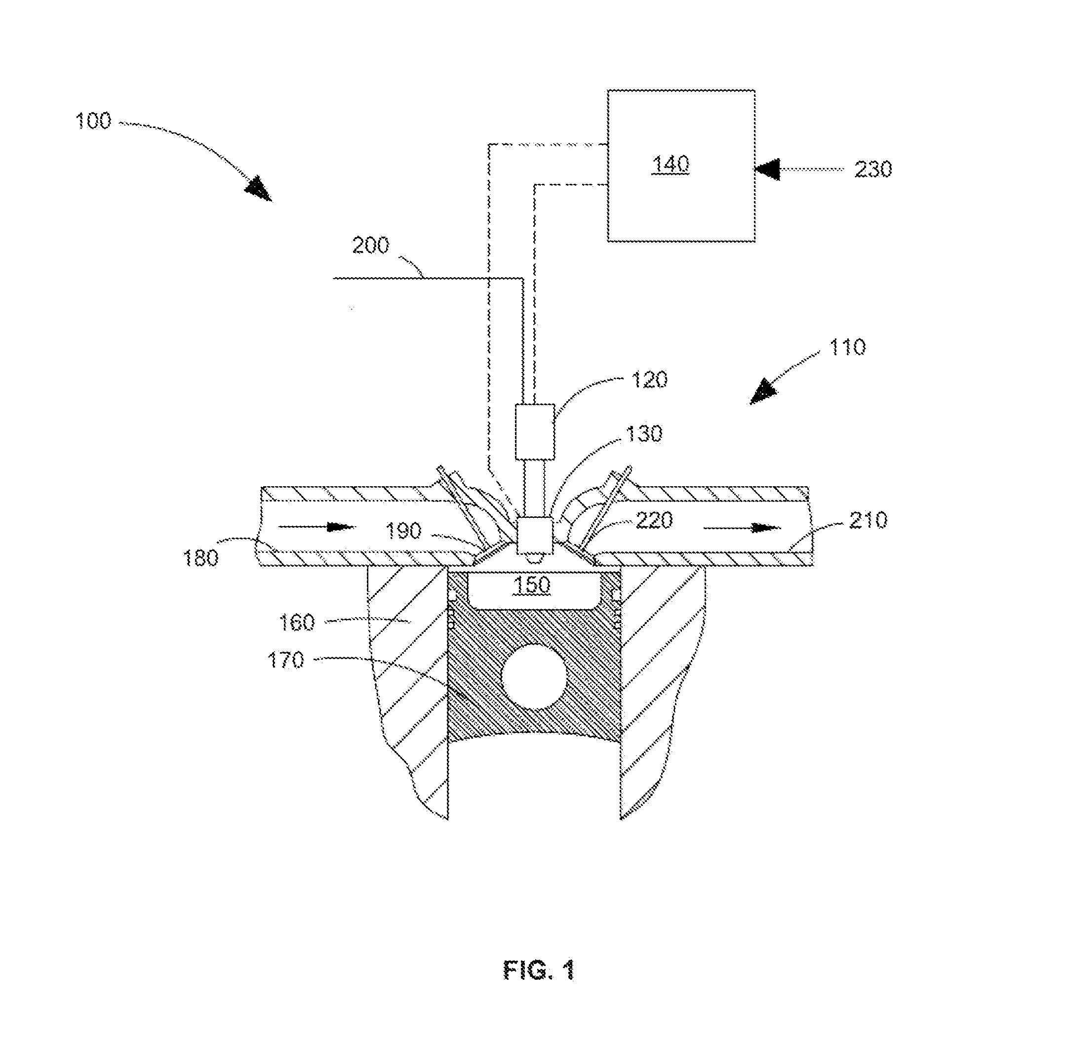
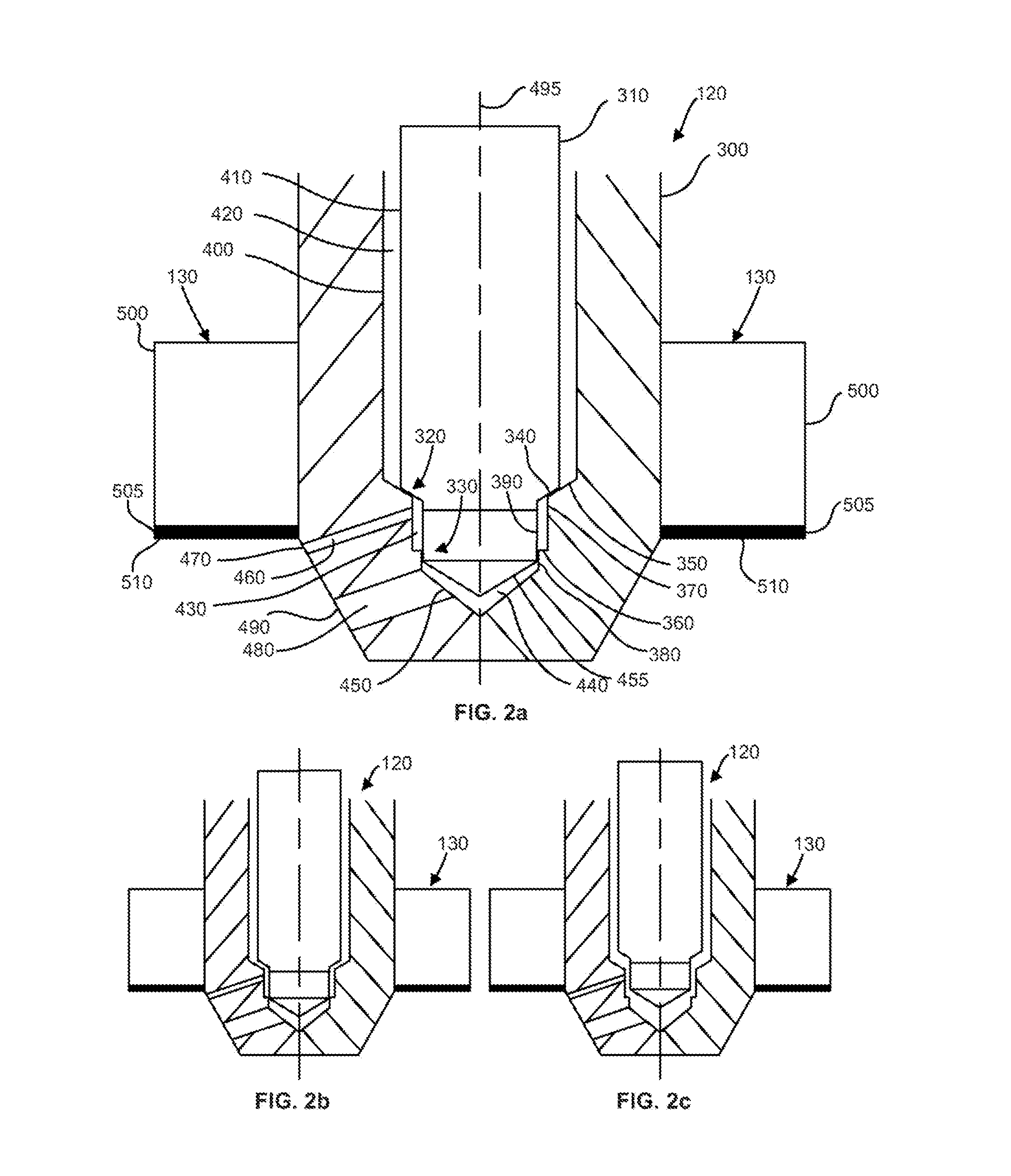
CROSS-REFERENCE TO RELATED APPLICATIONS[0001]This application is a continuation of International Application No. PCT / CA2013 / 050088 having an international filing date of Feb. 5, 2013, entitled “Apparatus And Method For Igniting A Gaseous Fuel In A Direct Injection Internal Combustion Engine”. The '088 international application claimed priority benefits, in turn, from Canadian Patent Application No. 2,767,247 filed on Feb. 7, 2012. The '088 international application is hereby incorporated by reference herein in its entirety.FIELD OF THE INVENTION[0002]The present invention relates to an apparatus and method for introducing and igniting a gaseous fuel in a Diesel-cycle internal combustion engine. The gaseous fuel is directly injected into a combustion chamber of the engine where a heated surface assists with ignition.BACKGROUND OF THE INVENTION[0003]Engines in which natural gas is directly injected into combustion chambers have achieved limited commercial success in the trucking indus...

Claims


Application Information

Patent Timeline
IPC IPC(8): F02P19/02F02D41/38F02D19/06F02D41/40F02B7/08
CPCF02D19/061F02D19/0644F02D19/0647F02P19/026F02D41/3827F02D41/403F02B7/08F02D19/0692F02M21/0275F02D41/0027Y02T10/44F02B23/0639F02M21/06Y02T10/32F02D19/024Y02T10/36F02D19/10F02M21/0269F02B23/0669Y02T10/125F02M21/0215F02M21/0263F02M45/086F02M61/08F02B23/0654F02M61/1813F02M61/1826F02M61/182F02M43/04F02M53/046F02B2023/103Y02T10/12Y02T10/30Y02T10/40
Inventor HUANG, JIANMUNSHI, SANDEEPMCTAGGART-COWAN, GORDON P.WAGER, DAVID R.
Owner WESTPORT FUEL SYST CANADA INC
Why Eureka
Try Eureka