
Internal combustion engine

Inactive Publication Date: 2005-03-22
TOYOTA JIDOSHA KK
View PDF27 Cites 34 Cited by
  • Summary
  • Abstract
  • Description
  • Claims
  • Application Information

AI Technical Summary

Benefits of technology

The present invention has been made in view of the above problems in the prior art. It is a first object of the present invention to provide a technique which, in an internal combustion engine mounted in a vehicle or the like, can improve the startability of the internal combustion engine and improve the combustion at the time of warm-up operation or the like. It is a second object of the present invention to provide a technique which makes it possible to supply reducing agent to an exhaust gas purifying catalyst without involving an unnecessary increase in fuel consumption amount.
Further, in the internal combustion engine of the present invention, the vaporized fuel is supplied to an exhaust gas purifying catalyst, so that it is possible for the exhaust gas purifying catalyst to utilize all the vaporized fuel as reducing agent. In this case, fuel is vaporized in the amount just required as reducing agent. As a result, it is possible to prevent an unnecessary increase in fuel consumption.

Problems solved by technology

5-81445B, when the combustion gas of the combustion heater or the rapid heating burner is supplied to the intake system at the start of the internal combustion engine, it is possible to raise the intake air temperature of the internal combustion engine with the heat of the combustion gas; however, a reduction in the amount of oxygen taken in the internal combustion engine involves an increase in the amount of carbon dioxide, so that the ignitionability and combustion stability of the fuel in the internal combustion engine are impaired, with the result that the startability of the internal combustion engine may deteriorate.
2000-186534A, when the combustion heater is operated at a rich air-fuel ratio, soot is accumulated in the combustion heater, which may lead to a deterioration in the performance of the combustion heater.
Further, when the combustion heater is operated at rich air-fuel ratio in order to supply reducing agent to the lean NOx catalyst, the surplus fuel component not used for the combustion in the combustion heater is supplied to the lean NOx catalyst as a reducing agent, which means waste of fuel for combustion in the combustion heater.
2000-186532A, when a reducing agent supply mechanism is provided in addition to the combustion heater, the internal combustion engine becomes rather hard to be mounted in a vehicle.

Method used


Image

  • Internal combustion engine
  • Internal combustion engine
  • Internal combustion engine

Examples


Embodiment Construction

Specific embodiments of the internal combustion engine of the present invention will now be described with reference to the accompanying drawings.

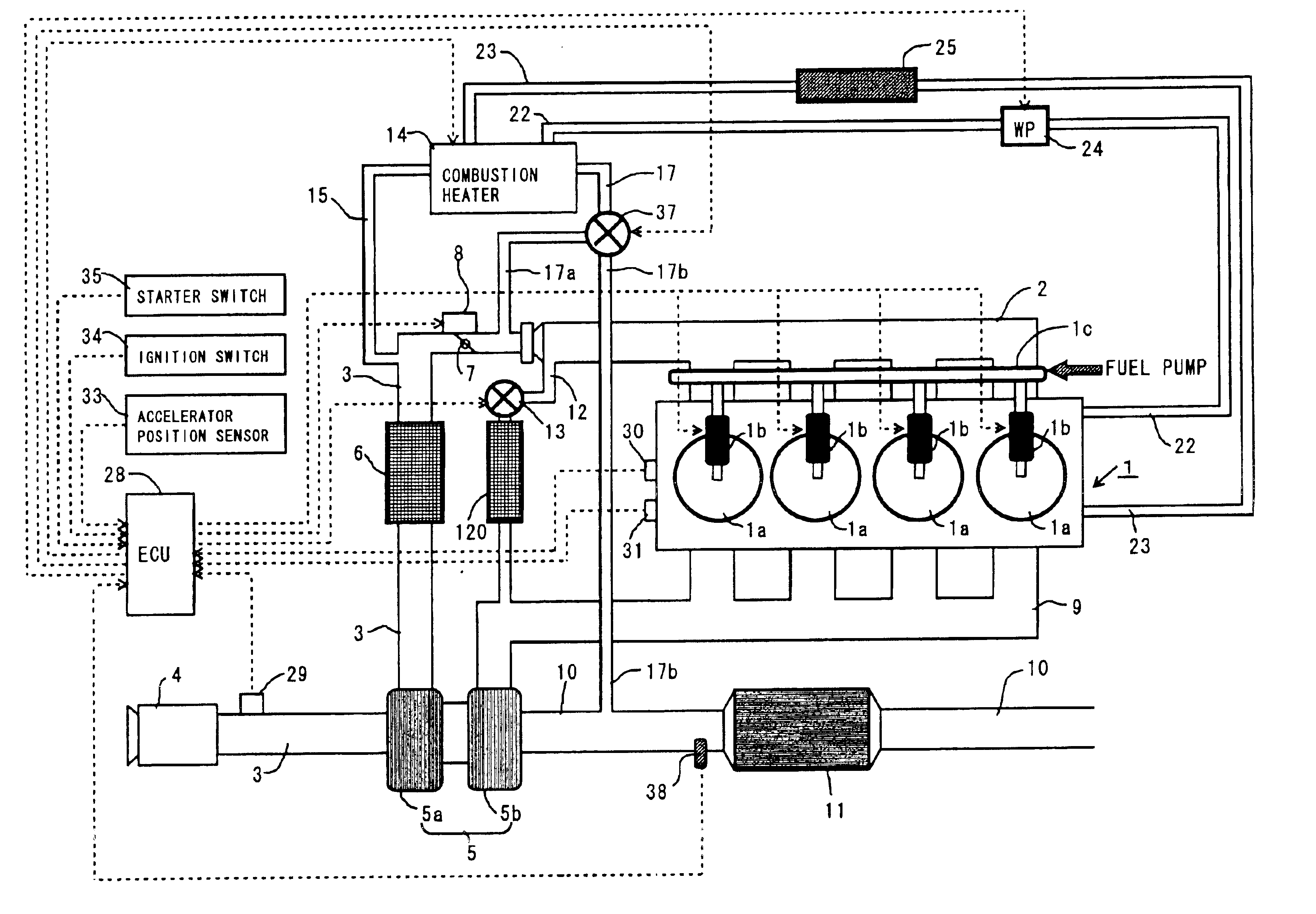
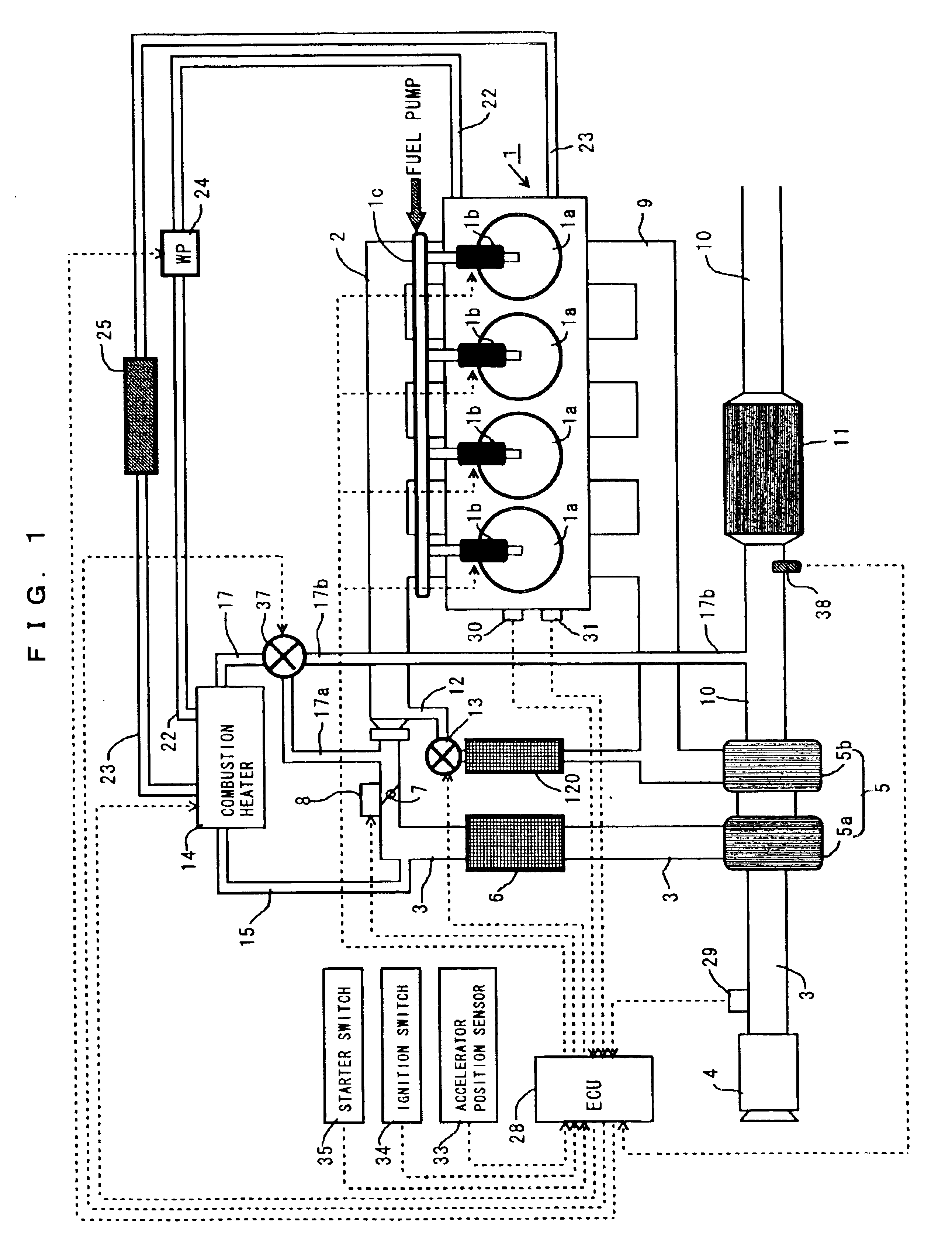
FIG. 1 is a diagram schematically showing the construction of an internal combustion engine to which the present invention is applied.

An internal combustion engine 1 is a water cooled cylinder-injection type diesel engine equipped with four cylinders 1a. Mounted to this internal combustion engine 1 are a crank position sensor 30 adapted to output a pulse signal each time a crankshaft (not shown) rotates by a predetermined angle, and a water temperature sensor 31 adapted to output an electric signal corresponding to the cooling water temperature water flowing through a water jacket (not shown).

Each cylinder 1a of the internal combustion engine 1 is equipped with a fuel injection valve 1b such that its nozzle hole faces a combustion chamber. Each fuel injection valve 1b communicates with an accumulator chamber (common rail chamber) 1c which ...


PUM


Abstract

Disclosed is an internal combustion engine which is to be mounted on automobiles or the like and in which an improvement has been achieved in terms of startability and combustion stability during warm-up operation. In an internal combustion engine of the type in which gas discharged from a combustion heater is introduced into an intake passage of the internal combustion engine, a fuel vaporizing glow plug is operated during the period from the starting of the internal combustion engine to the occurrence of complete explosion, whereby unburned vaporized fuel is supplied from the combustion heater to the internal combustion engine.

Description

BACKGROUND OF THE INVENTION1. Field of the InventionThe present invention relates to an internal combustion engine to be mounted on automobiles or the like.2. Description of the Related ArtRecently, regarding internal combustion engines to be mounted on automobiles or the like, there has been proposed a technique according to which a combustion heater, a rapid heater or the like is provided in order, for example, to improve the performance of the room heating device when the engine is in the cold state or to promote the warming-up of the internal combustion engine.Known examples of the above-mentioned technique include “an internal combustion engine having a combustion heater” as disclosed in JAPANESE PATENT LAID-OPEN PUBLICATION NO. 2000-240519A, “an internal combustion engine having a lean NOx catalyst” as disclosed in JAPANESE PATENT LAID-OPEN PUBLICATION NO. 2000-186531A, “an internal combustion engine having a lean NOx catalyst” as disclosed in JAPANESE PATENT LAID-OPEN PUBLICA...

Claims


Application Information

Patent Timeline
IPC IPC(8): F02D41/00F02D41/06F02P19/00F02M31/125F02M31/02F02M31/18F02D41/38F02B37/00F02M31/04F01N3/36F02M31/06
CPCF02D41/0027F02D41/003F02D41/06F02M31/125F02M31/186F02P19/00F02B37/00F02D41/0007F02D41/1454Y02T10/126F02D41/3836F02D2200/602F02M31/183F02D41/187Y02T10/12
Inventor SUZUKI, MAKOTO
Owner TOYOTA JIDOSHA KK
Learn More