
Electrophotographic photoreceptor and image forming apparatus including the same

a photoreceptor and photoreceptor technology, applied in the direction of electrographic process apparatus, instruments, corona discharge, etc., can solve the problems of inhibiting the reduction of sensitivity, deterioration of the electric properties of the photoreceptor, and insufficient dispersion stability, so as to improve the dispersion stability, and improve the effect of dispersion stability

Active Publication Date: 2015-01-15
SHARP KK
View PDF1 Cites 4 Cited by
  • Summary
  • Abstract
  • Description
  • Claims
  • Application Information

AI Technical Summary

Benefits of technology

The present invention relates to a method of improving the performance of electrophotographic photoreceptors by adding oxygen-containing fluorinated fine particles to the surface of the photoreceptor. The added particles provide stability and high wear resistance, while the charge transport material used in combination with the particles ensures high image quality and stable electrical properties over a long period of time. The use of oxygen-containing fluorinated fine particles and a charge transport material with a wide range of ionization potential further enhances the dispersion stability of the photoreceptor. Overall, the invention provides a photoreceptor with improved performance and stability for use in image forming apparatuses.

Problems solved by technology

As described above, it is unavoidable to use a dispersant when fluorinated fine particles are added to the surface layer of the photoreceptor, and the addition of a dispersant is accompanied by deterioration of the electric properties of the photoreceptor.
Besides, sufficient dispersion stability has not been ensured yet even with the addition of a dispersant.
On the other hand, use of the fluorinated fine particles in combination with a charge transport material having better responsiveness and electric properties but having relatively low ionization potential for inhibiting deterioration of the electric properties of the photoreceptor due to the use of a dispersant can inhibit the sensitivity reduction but cannot provide high image quality, because the material is vulnerable to damage from oxidized gas and likely to cause an image defect.
At present, therefore, it is impossible to ensure both the extended life and the higher image quality.

Method used


Image

  • Electrophotographic photoreceptor and image forming apparatus including the same
  • Electrophotographic photoreceptor and image forming apparatus including the same
  • Electrophotographic photoreceptor and image forming apparatus including the same

Examples


embodiment 1

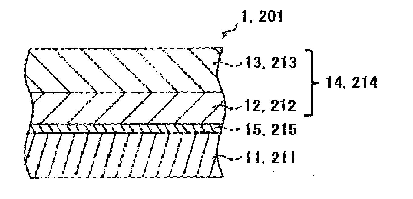
[0064]FIG. 1 is a schematic sectional view showing a configuration of an electrophotographic photoreceptor according to Embodiment 1 of the present invention. An electrophotographic photoreceptor 1, 201 according to Embodiment 1 (hereinafter, abbreviated as “photoreceptor”) is a multilayered photoreceptor including, in sequence, a cylindrical conductive substrate 11, 211 formed of a conductive material; an undercoat layer 15, 215; and a photosensitive layer 14, 214 including a charge generation layer 12, 212 containing a charge generation material and a charge transport layer 13, 213 containing a charge transport material stacked in this order.

Conductive Substrate (Hereinafter, May be Referred to as “Conductive Support”)

[0065]The conductive substrate 11, 211 plays a role as an electrode of the photoreceptor 1 and functions as a supporting member for the layers disposed thereon, that is, the undercoat layer 15, 215 and the photosensitive layer 14, 214.

[0066]While the conductive subst...

embodiment 2

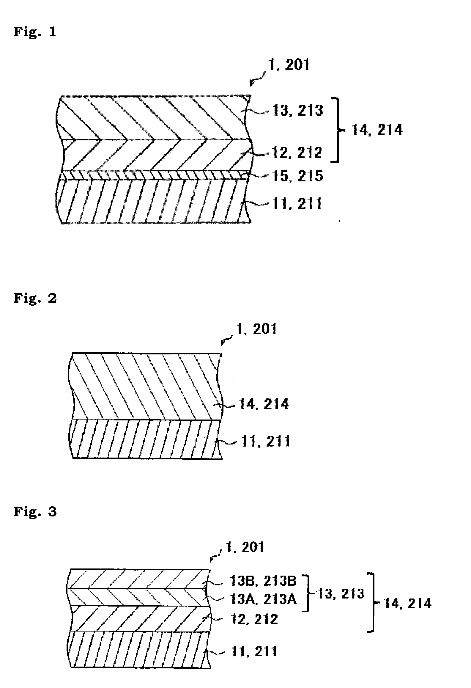
[0156]As Embodiment 1, an embodiment has been described in which the photosensitive layer 14, 214 is a multilayered photosensitive layer including the charge generation layer 12, 212 and the charge transport layer 13, 213. In another embodiment, however, the photosensitive layer 14, 214 may be a single layer, that is, a monolayer photosensitive layer as shown in FIG. 2.

[0157]Specifically, the photoreceptor 1, 201 may be formed from the cylindrical conductive substrate 11, 211 made of a conductive material, and a photosensitive layer 14, 214 which is a layer stacked on an outer circumferential surface of the conductive substrate 11, 211 and which contains a charge generation material and a charge transport material.

embodiment 3

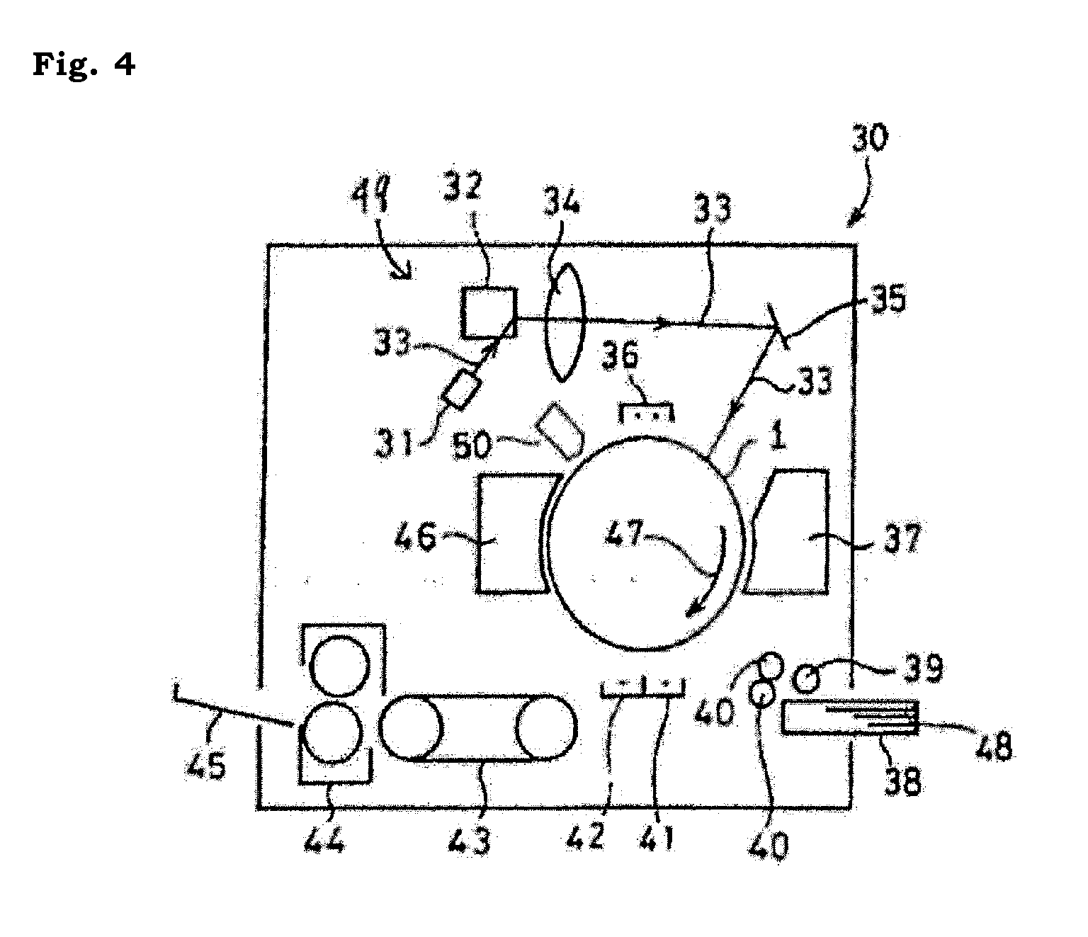
[0158]In another embodiment, the charge transport layer 13, 213 may be formed from a plurality of layers as shown in FIG. 3.

[0159]In the present embodiment, specifically, the charge transport layer is formed from two different charge transport layers 13A (213A) and 13B, 213B stacked one on top of the other, and oxygen-containing fluorinated fine particles are added to the charge transport layer 13B, 213B constituting the outermost surface. That is, FIG. 3 shows an embodiment in which the charge transport layer 13, 213 is formed from the first charge transport layer 13A, 213A and the second charge transport layer 13B, 213B, the first charge transport layer 13A, 213A and the second charge transport layer 13B, 213B have different charge transport material contents, and the second charge transport layer 13B, 213B contains filler particles.

[0160]When the charge transport layer 13, 213 is formed from a plurality of layers stacked one on top of the other as described above, filler particle...


PUM

PropertyMeasurementUnit
median sizeaaaaaaaaaa
ionization potentialaaaaaaaaaa

Abstract

An electrophotographic photoreceptor having a photosensitive layer formed on a conductive substrate, wherein the photosensitive layer contains oxygen-containing fluorinated fine particles in a surface layer thereof, and the oxygen-containing fluorinated fine particles have an oxygen composition ratio of 0.9 to 3.0% by atom based on the whole composition of the fine particles according to an X-ray fluorescence composition analysis.

Description

CROSS-REFERENCE TO RELATED APPLICATION[0001]This application is related to Japanese Patent Application Nos. 2013-143634 and 2013-143644 filed on 9 Jul., 2013, whose priorities are claimed under 35 USC §119, and the disclosures of which are incorporated by reference in their entirety.BACKGROUND OF THE INVENTION[0002]1. Field of the Invention[0003]The present invention relates to an electrophotographic photoreceptor and an image forming apparatus including the same. More particularly, the present invention relates to an electrophotographic photoreceptor in which a photosensitive layer contains oxygen-containing fluorinated fine particles in a surface layer thereof, as well as to an electrophotographic photoreceptor in which a photosensitive layer contains oxygen-containing fluorinated fine particles in a surface layer thereof and the photosensitive layer contains a charge transport material having an ionization potential of 5.25 to 5.70 eV, and to an image forming apparatus including ...

Claims


Application Information

Patent Timeline
Patent Type & Authority Applications(United States)
IPC IPC(8): G03G15/00
CPCG03G5/00G03G5/071G03G5/0503G03G5/0539G03G5/0592G03G5/0596G03G5/14708G03G5/14726G03G5/14791
Inventor FUKUSHIMA, KOTAROKUMAZAWA, KIMIKOTORIYAMA, KOICHIKURAUCHI, TAKAHIROKANAZAWA, TOMOKOIIBACHI, CHIKAKOMATSUO, RIKIYA
Owner SHARP KK
Learn More