Power storage apparatus and vehicle with power storage apparatus mounted thereon

a technology of power storage apparatus and power storage device, which is applied in the direction of battery, wound/folded electrode electrode, sustainable manufacturing/processing, etc., can solve the problems of processing errors, difficult to consistently form active material layer in a fixed region, active material layer to be formed on the electrode tab, etc., to improve the usage rate of active material and improve energy density.

Active Publication Date: 2015-01-15
TOYOTA IND CORP
View PDF7 Cites 5 Cited by
  • Summary
  • Abstract
  • Description
  • Claims
  • Application Information

AI Technical Summary

Benefits of technology

The present invention relates to a power storage device that improves the usage rate of the active material and increases the energy density. The device includes a positive electrode tab and a negative electrode tab. In the negative electrode sheet, a portion corresponding to the location near the positive electrode tab is irrelevant to improving the battery capacity. The technical effect of this design is that it saves the positive active material and improves the energy density of the power storage device. Additionally, the design allows for the reduction of the thin metal plate used in the negative electrode sheet, resulting in improved energy density.

Problems solved by technology

Under this condition, it is difficult to consistently form the active material layer in a fixed region.
This often causes processing errors in the formation region (formation location) of the active material layer.
Thus, for example, in a positive electrode sheet, the processing error may cause the active material layer to be formed on the electrode tab.
This may decrease the energy density of the power storage device.

Method used


Image

  • Power storage apparatus and vehicle with power storage apparatus mounted thereon
  • Power storage apparatus and vehicle with power storage apparatus mounted thereon
  • Power storage apparatus and vehicle with power storage apparatus mounted thereon

Examples


Embodiment Construction

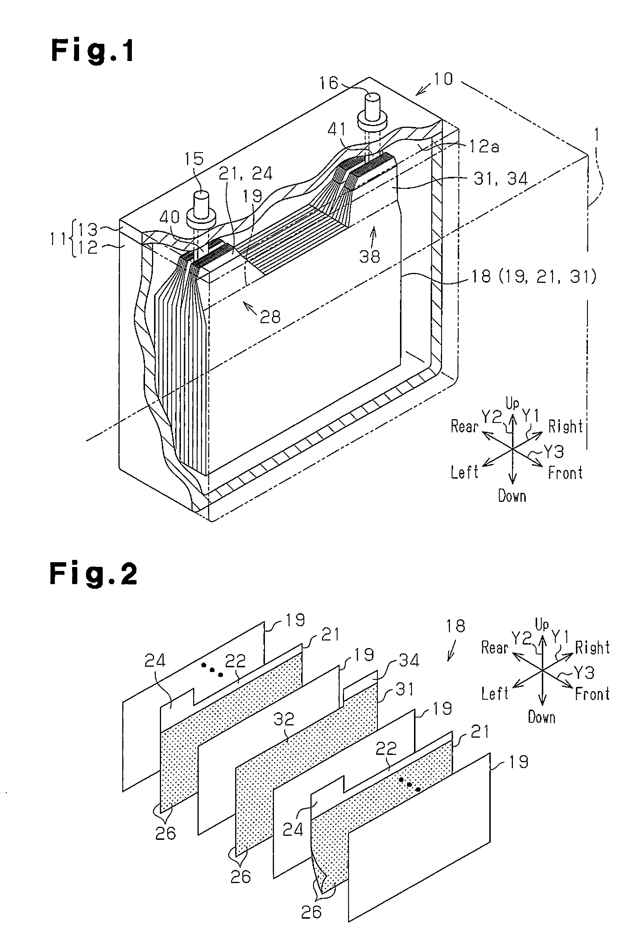
[0017]One embodiment of the present invention will now be described with reference to FIGS. 1 to 3(b).

[0018]As shown in FIG. 1, a rechargeable battery 10, which serves as a power storage device, is installed in a vehicle such as an industrial vehicle or a passenger vehicle. The rechargeable battery 10 includes a case 11, which has a generally cuboid shape and has a low profile as a whole. The case 11 includes a main body member 12, which is tubular and includes a closed end (tetragonal tube in the present embodiment), and a plate-like (tetragonal plate-like in the present embodiment) cover member 13. The cover member 13 is coupled to the main body member 12 to seal an opening 12a of the main body member 12. The main body member 12 and the cover member 13 are each formed from a metal (for example, stainless steel or aluminum). Hereinafter, in the present description, the longitudinal direction of the case 11 indicated by arrow Y1 is defined as a left-right direction or a lateral dire...


PUM

PropertyMeasurementUnit
degree of freedomaaaaaaaaaa
lengthaaaaaaaaaa
structureaaaaaaaaaa

Abstract

A power storage device includes an electrode assembly formed by stacking a positive electrode sheet, a negative electrode sheet, and a sheet-like separator arranged between the positive and negative electrode sheets. The positive electrode sheet includes a positive electrode thin metal plate, which includes a first positive electrode edge and a second positive electrode edge. A surface of the positive electrode sheet includes a positive electrode application region and a positive electrode non-application region. The negative electrode sheet includes a negative electrode thin metal plate including a first negative electrode edge and a second negative electrode edge. A positive electrode border, which is a border between the positive electrode application region and the positive electrode non-application region, is located between the first positive electrode edge and the second positive electrode edge. The positive electrode border is located between the first negative electrode edge and the second negative electrode edge.

Description

FIELD OF THE INVENTION[0001]The present invention relates to a power storage device and a vehicle in which the power storage device is installed.BACKGROUND OF THE INVENTION[0002]In the prior art, a lithium-ion rechargeable battery and a nickel-metal hydride rechargeable battery are each known as a rechargeable battery that is a type of a power storage device. For example, in a lithium-ion rechargeable battery, an electrode assembly, which is formed by stacking or winding positive electrode sheets and negative electrode sheets, is accommodated in a case. In the electrode assembly, the positive electrode sheets and the negative electrode sheets form a layered structure. The positive electrode sheets and the negative electrode sheets each include a thin metal plate. An electrode tab extends from one edge of the thin metal plate. For example, refer to patent document 1.[0003]In a rechargeable battery described in patent document 1, in each electrode sheet, an active material layer is fo...

Claims


Application Information

Patent Timeline
Patent Type & Authority Applications(United States)
IPC IPC(8): H01M10/04H01M4/02H01M50/531
CPCH01M10/0413H01M2220/20H01G11/72H01G11/76H01M10/0431H01G11/22H01M50/531H01M4/02H01G11/82Y02E60/10Y02P70/50Y02E60/13
Inventor MINAGATA, ATSUSHI
Owner TOYOTA IND CORP
Why Eureka
Try Eureka