Centrifugally cast composite roll and its production method

a technology of centrifugal casting and composite rolls, applied in the direction of manufacturing tools, transportation and packaging, chemistry apparatuses and processes, etc., can solve the problems of low productivity, poor surface quality of rolled sheets, and insufficient wear resistance of clutch portions, etc., and achieve the effect of improving attrition resistan

Active Publication Date: 2014-12-25
HITACHI METALS LTD
View PDF9 Cites 5 Cited by
  • Summary
  • Abstract
  • Description
  • Claims
  • Application Information

AI Technical Summary

Benefits of technology

[0007]Accordingly, an object of the present invention is to provide a centrifugally cast composite roll having improved attrition resistance in the driver-side shaft portion while maintaining the machinability of the follower-side shaft portion, and its production method.

Problems solved by technology

When damages such as wear and surface roughening, etc. occur in a surface layer of the outer layer 1 of the hot-rolling roll 10 by a thermal and mechanical load due to contact with a sheet to be rolled, a rolled sheet has poor surface quality.
The frequent exchange of the composite rolls 10 results in frequent interruption of rolling, resulting in low productivity.
However, this clutch portion still has insufficient wear resistance.
In addition, the end-to-end casting connection of the clutch portion to the shaft portion causes such a problem that foreign matter, etc. are likely introduced into an interface therebetween, resulting in casting defects.
Further needed are flat cutting of casting-connected portions, setting a mold around portions to be casting-connected, and the melting and casting steps of spheroidal graphite cast iron for the clutch portion different from the inner layer, resulting in a higher production cost.
There is a further problem that if the driver-side shaft portion 22 and the follower-side shaft portion 23 were formed by the same hard material, the follower-side shaft portion 23 not required to be as hard as the driver-side shaft portion 22 would be unnecessarily hard, resulting in poor machinability.

Method used


Image

  • Centrifugally cast composite roll and its production method
  • Centrifugally cast composite roll and its production method
  • Centrifugally cast composite roll and its production method

Examples


example 4

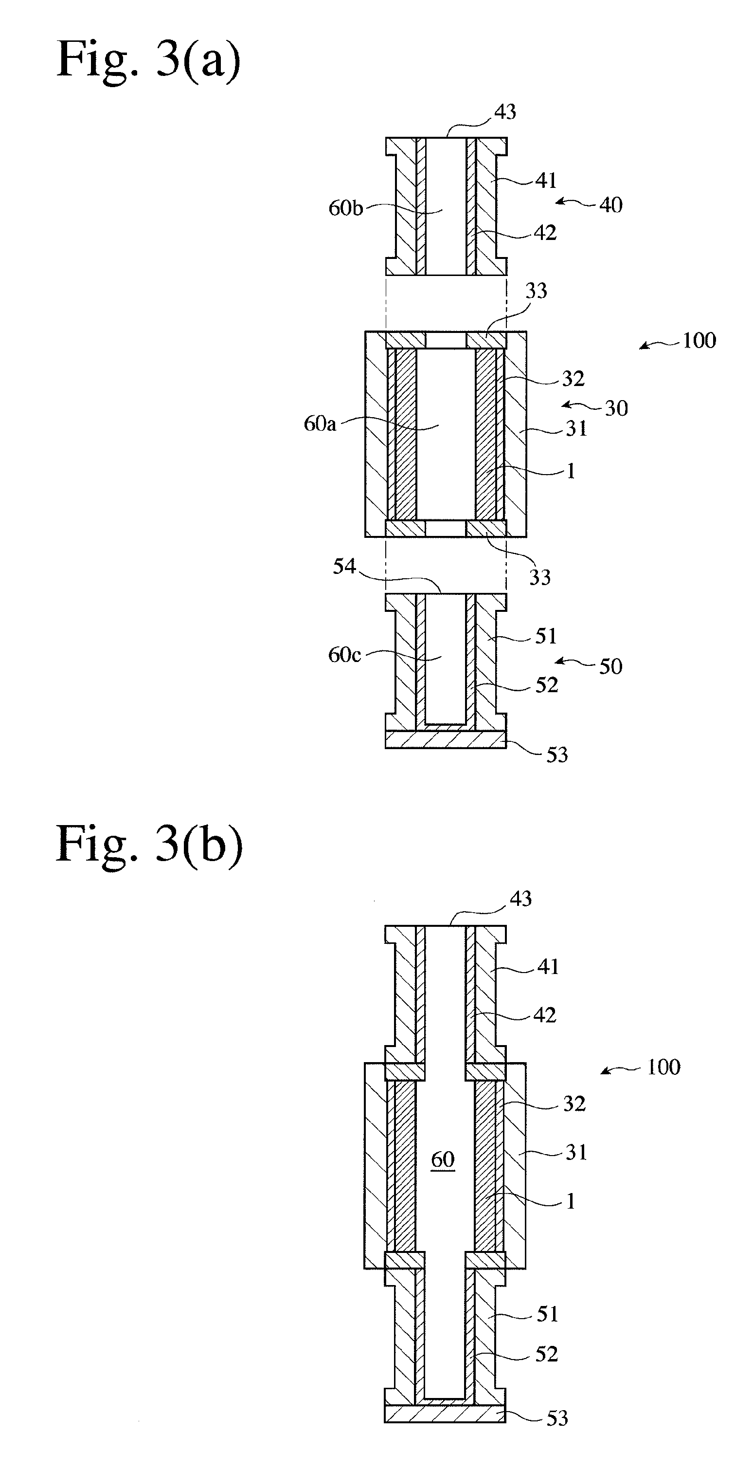
[0116]A composite roll was formed in the same manner as in Example 1, except that the cylindrical mold 30 was erected upright, after an intermediate layer (thickness: 20 mm) having the composition shown in Table 1 was formed on an inner surface of the outer layer 1. Ultrasonic inspection confirmed that the outer layer 1 was well fused to the inner layer 2 via the intermediate layer.

[0117]With respect to Examples 1-4, and Comparative Example 1 and 2, the casting temperatures of the outer layer, the inner layer and the intermediate layer, and the average elevating speed of an inner layer melt surface in the lower mold 50 for the driver-side shaft portion 22, the cylindrical mold 30 for the roll body portion 21 and the upper mold 40 for the follower-side shaft portion 23 are shown in Table 2. The average elevating speed of the inner layer melt surface was determined from the measured weight of the inner layer melt and the measured casting time. Also, with respect to each sample cut out...


PUM

PropertyMeasurementUnit
elevating speedaaaaaaaaaa
mass ratioaaaaaaaaaa

Abstract

A centrifugally cast composite roll comprising an outer layer formed by a centrifugal casting method, and an inner layer made of ductile cast iron and integrally fused to the outer layer; the outer layer being made of an Fe-based alloy having a chemical composition comprising by mass at least 0.8-3.0% of Cr, 1.5-6.0% of Mo, and 1.8-5.5% of V, and a metal structure in which the area ratio of graphite is 0.3-10%; the inner layer comprising a roll body portion fused to the outer layer, and shaft portions integrally extending from both ends of the roll body portion; and the total amount of Cr, Mo and V being 0.15-2.0% by mass in end portions of both shaft portions, and the difference in the total amount of Cr, Mo and V between one shaft portion and the other shaft portion being 0.2% or more by mass.

Description

FIELD OF THE INVENTION[0001]The present invention relates to a centrifugally cast composite roll having a composite structure comprising an outer layer formed by a centrifugal casting method and a tough inner layer fused to the outer layer, and its production method.BACKGROUND OF THE INVENTION[0002]As shown in FIGS. 1 and 2, a hot-rolling composite roll 10 comprises an outer layer 1 coming into contact with a sheet to be rolled, and an inner layer 2 fused to an inner surface of the outer layer 1 and made of a different material from that of the outer layer 1. The inner layer 2 comprises a roll body portion 21 fused to the outer layer 1, and a driver-side shaft portion 22 and a follower-side shaft portion 23 integrally extending from both ends of the roll body portion 21. An end portion of the driver-side shaft portion 22 is integrally provided with a clutch portion 24 for conveying a driving torque. An end portion of the follower-side shaft portion 23 is integrally provided with a p...

Claims


Application Information

Patent Timeline
Patent Type & Authority Applications(United States)
IPC IPC(8): B22D13/02B32B15/01
CPCB32B15/011B22D13/026B22D13/02C22C37/06B21B27/032C22C37/08C22C37/10B22D13/023B22D19/16Y10T428/12958B21B27/00C22C37/00
Inventor ODA, NOZOMUSEGAWA, TAKAYUKINOZAKI, YASUNORIHATTORI, TOSHIYUKI
Owner HITACHI METALS LTD
Why Eureka
Try Eureka