Mesoporous fcc catalysts with excellent attrition resistance

a technology of mesoporous fcc and cracking catalyst, which is applied in the field of new fluid catalytic cracking catalysts, can solve the problems of increasing the cost of catalyst to the refiner, physical breaking down of catalyst into even smaller particles called “fines”, and achieving high overall pore volume, improved attrition resistance, and improved attrition resistance

Inactive Publication Date: 2015-04-16
BASF CORP
View PDF6 Cites 0 Cited by
  • Summary
  • Abstract
  • Description
  • Claims
  • Application Information

AI Technical Summary

Benefits of technology

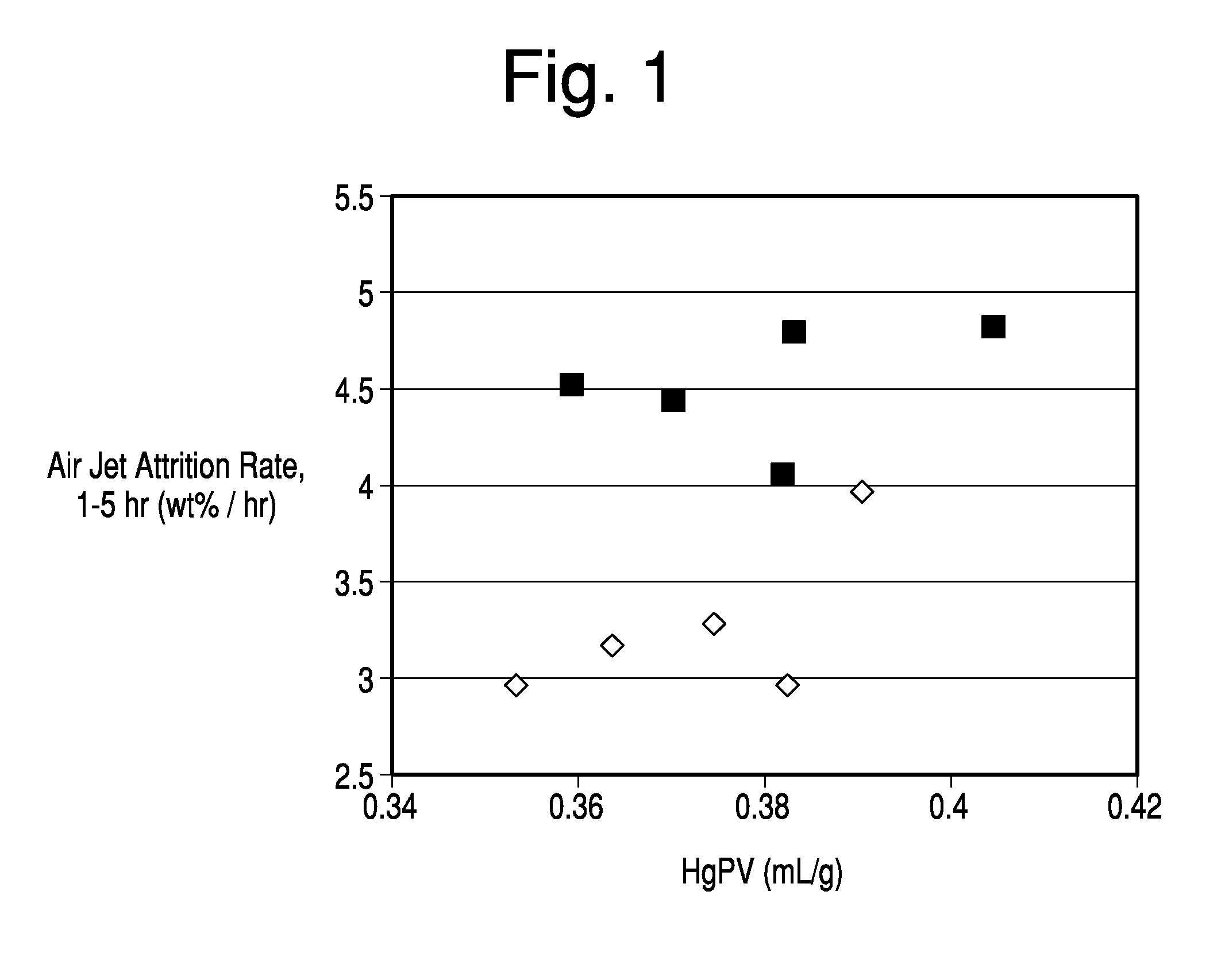
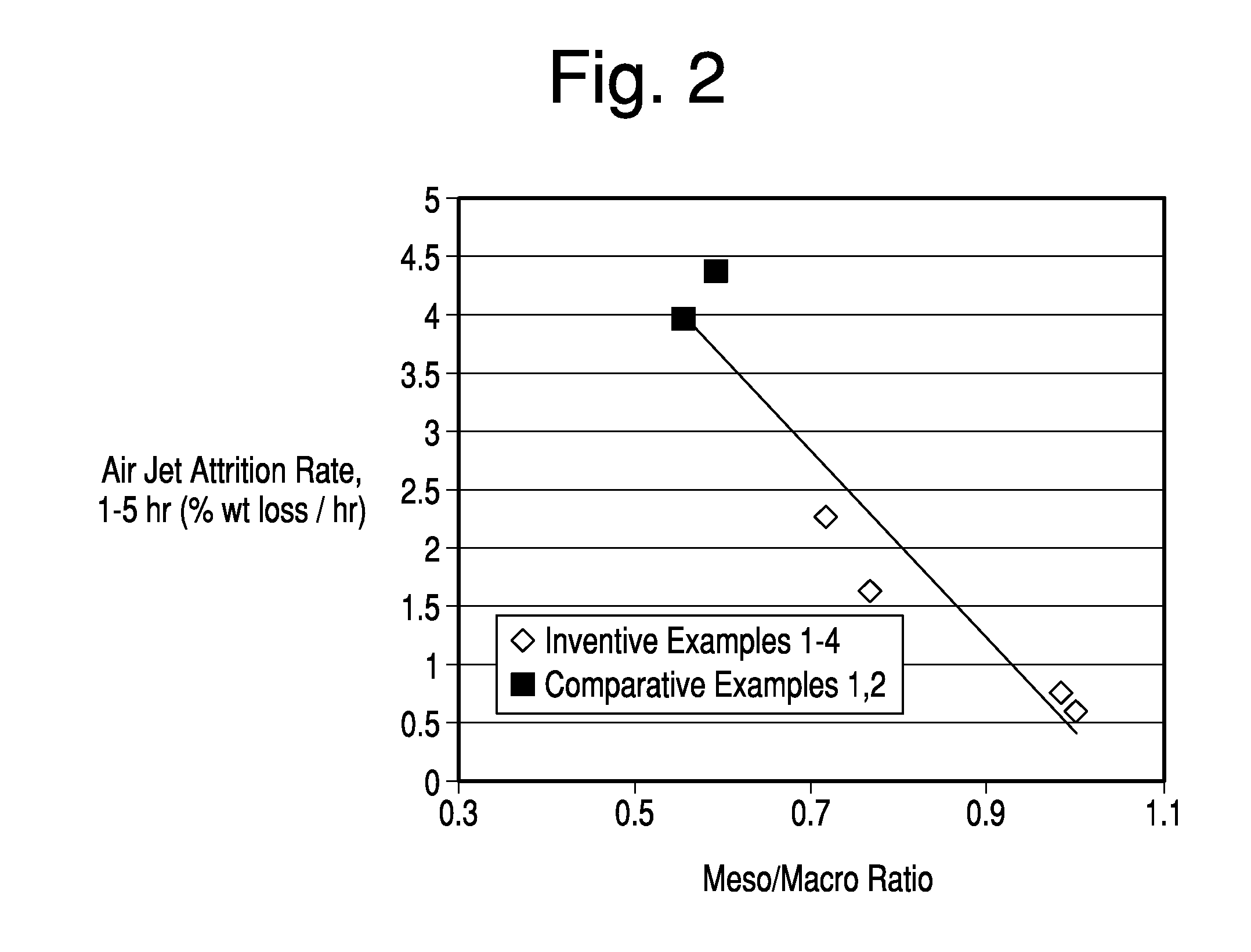
[0026]Improved attrition resistance, as well as controlled pore volume is now provided to an FCC catalyst from a microsphere formed by combining a matrix precursor treated with a polyphosphate and a hydrous kaolin slurry treated with a cationic polyelectrolyte. The combined treatment with the polyphosphate and cationic polyelectrolyte yields unexpected improvements in attrition resistance, while maintaining high overall pore volume, even as the ratio of meso pore volume to macro pore volume of the formed FCC catalyst increases.

Problems solved by technology

As the hydrocarbon feed is cracked in the presence of cracking catalyst to form gasoline and olefins, undesirable carbonaceous residue known as “coke” is deposited on the catalyst.
These cycles of cracking and regeneration at high flow rates and temperatures have a tendency to physically break down the catalyst into even smaller particles called “fines”.
While the initial size of the particles can be controlled by controlling the initial spray drying of the catalyst, if the attrition resistance is poor, the catalytic cracking unit may produce a large amount of the 0-20 micron fines which should not be released into the atmosphere.
Those skilled in the art also appreciate that excessive generation of catalyst fines increases the cost of catalyst to the refiner.
Excess fines can cause increased addition of catalyst and dilution of catalytically viable particles.
For example, such a result is contrary to the prior art disclosures that low pore volumes “can lead to selectivity losses due to diffusional restrictions.”
Thus, while typical FCC catalysts formed by mechanically incorporating the zeolite within a matrix may have been more porous, the reaction time in prior art FCC risers did not yield any advantage in activity or selectivity.
Assertions made to the contrary were inconsistent with the facts and easily dismissed as self-serving.
Several of the designs do not even employ a riser, further reducing contact time to below one second.
The processing of increasingly heavier feeds in FCC type processes and the tendency of such feeds to elevate coke production and yield undesirable products have also led to new methods of contacting the feeds with catalyst.
Unfortunately, it has been found that the API gravity of the bottoms formed during short contact time (“SCT”) often increases after a unit revamp, leading some to suggest that the heaviest portion of the hydrocarbon feed takes longer to crack.
As the porosity of a microsphere is increased, however, the rate at which the microsphere fractures and attrits into finer particles within the FCC unit operating environment increases; resulting in increased fresh catalyst addition rates and increased particulate emission from the unit.

Method used


Image

  • Mesoporous fcc catalysts with excellent attrition resistance
  • Mesoporous fcc catalysts with excellent attrition resistance
  • Mesoporous fcc catalysts with excellent attrition resistance

Examples


example 1

[0064]This example and corresponding data were produced and described in the commonly assigned U.S. application Ser. No. 13 / 042,790. The procedure and results are mentioned here for comparative purposes. Hydrous kaolin slurry consisting of particles with greater than 70% having an equivalent spherical diameter less than 2 μm as measured by Sedigraph 5200 and less than 0.5% particles captured on a 325-mesh screen was utilized. The hydrous kaolin in the amount of 37.5 dry wt. % was mixed with calcined kaolin in the amount of 62.5 dry wt. % to produce five inventive samples, each of which had a total slurry solids level of ˜50% by weight. The physical properties of the kaolins are shown in Tables 1 and 2.

[0065]The incorporated calcined kaolin consisted of material that was heated beyond the characteristic exothermic transition at ˜950° C. to form spinel, mullite or a combination of spinel and mullite. The Mullite index (MI) is the ratio of the mullite peak in the kaolin sample to a 100...

example 2

[0073]Hydrous kaolin slurry consisting of particles with greater than 70% having an equivalent spherical diameter less than 2 μm as measured by Sedigraph 5200 and less than 0.5% particles captured on a 325 mesh screen was utilized. The hydrous kaolin in the amount of 46 to 52 dry wt. % was mixed with calcined kaolin in the amount of 48 to 54 dry wt. % to produce six inventive samples, each of which had a total slurry solids level of ˜50% by weight.

[0074]The calcined kaolin components for both the Inventive and Comparative samples were formed from the same hydrous kaolin slurry source. However, for the Inventive samples, a 37.0 wt % ammonium polyphosphate solution was added at 0.15 dry wt % as available phosphate to the hydrous kaolin slurry prior to calcination. For the Comparative samples the calcined kaolin was not pre-treated with phosphate. The physical properties of note related to the hydrous and calcined kaolin components are detailed in Table 1 of Example 1 and Table 7 below...

example 3

[0084]FIG. 4 compares the air jet attrition rates of Comparative FCC catalysts plotted as squares, including a commercial catalyst prepared in accordance with the teachings of U.S. Pat. No. 6,943,132, versus the Inventive samples noted by the data plotted as dots. The Comparative and Inventive samples demonstrated were prepared according to the procedures outlined in Example 2, but are not of the samples as described in Example 2. Specifically, in FIG. 4, for Inventive Samples, ammonium polyphosphate was added at a dosage of 0.15 wt % as available phosphate to the hydrous kaolin slurry prior to forming the calcined kaolin used in the subsequent blending step. Polyamine was added to the blend of hydrous and calcined kaolin at a dosage of 1 lb. / ton. In each Inventive example, the amount of polyamine treated kaolin in the microsphere equaled 48 to 52 wt. % and the polyphosphate treated kaolin equaled 52 to 48 wt. % of the total kaolin content of the microsphere. As shown in FIG. 4, the...


PUM

PropertyMeasurementUnit
particle sizeaaaaaaaaaa
wt. %aaaaaaaaaa
temperatureaaaaaaaaaa

Abstract

This application discloses a mesoporous catalyst formed by combining a matrix precursor treated with a polyphosphate, and a metallic oxide treated with a cationic electrolyte. The combined treatment with the polyphosphate and cationic polyelectrolyte yields unexpected improvements in attrition resistance, while maintaining high overall pore volume, even as the ratio of meso pore volume to macro pore volume of the formed FCC catalyst increases.

Description

BACKGROUND OF THE INVENTION[0001]The present invention relates to novel fluid catalytic cracking catalysts comprising microspheres containing Y-faujasite zeolite and having exceptionally high activity and other desirable characteristics, methods for making such catalysts and the use of such catalysts for cracking petroleum feedstocks, particularly under short residence time processes.[0002]Since the 1960's, most commercial fluid catalytic cracking catalysts have contained zeolites as an active component. Such catalysts have taken the form of small particles, called microspheres, containing both an active zeolite component and a non-zeolite component. Frequently, the non-zeolitic component is referred to as the matrix for the zeolitic component of the catalyst. The non-zeolitic component is known to perform a number of important functions, relating to both the catalytic and physical properties of the catalyst. Oblad described those functions as follows: “The matrix is said to act as ...

Claims


Application Information

Patent Timeline
Patent Type & Authority Applications(United States)
IPC IPC(8): B01J29/08
CPCB01J29/084B01J35/023B01J35/1019B01J35/1038B01J35/1061B01J37/0018B01J37/0045B01J2229/36B01J2229/42B01J2229/64C10G11/05B01J21/12B01J23/005B01J27/14B01J35/10
Inventor SIGMAN, MICHAELKEWESHAN, CHARLESWILLIS, MITCHELL
Owner BASF CORP
Why Eureka
Try Eureka