Substrate material of iron-nickel alloy metal foil for cigs solar cells
a technology of iron-nickel alloy metal foil and substrate material, which is applied in the direction of sustainable manufacturing/processing, final product manufacturing, electrolysis processes, etc., can solve the problems of increasing the width of the metal substrate material being processed, difficult to handle, and interlayer separation, and achieves the effect of simple process system
- Summary
- Abstract
- Description
- Claims
- Application Information
AI Technical Summary
Benefits of technology
Problems solved by technology
Method used
Image
Examples
example 1
[0041]An alloy metal foil substrate material composed of Fe-46 wt % Ni was produced using an electrolyte solution having the following composition and the electroforming apparatus shown in FIG. 1. Specifically, the electrolyte solution contained 200 g / L of nickel sulfamate, 20 g / L of iron (II) chloride 4-hydrate, 20 g / L of boronic acid, 0.5 g / L of sodium lauryl sulfate, 2 g / L of saccharin and 1 g / L of an antioxidant (ascorbic acid) and had a pH of 3.0. The electrolyte solution was maintained at a temperature of 60° C. and controlled to a current density of 56 mA / cm2, thereby producing a metal foil substrate material composed of Fe-46 wt % Ni and having a thickness of 30 μm. The produced substrate material had a grain size of 15-20 μm. When the produced substrate material was subjected to a structure stabilization process under a hydrogen atmosphere at a temperature of 400˜1000° C. for 1 hour, the grain size increased to 0.1-10 μm.
[0042]In the cases in which (a) the produced Fe—Ni su...
example 2
[0043]An alloy metal foil substrate material composed of Fe-48 wt % Ni was produced in a manner similar to that described in Example 1 using an electrolyte solution having a composition controlled to provide Fe-48 wt % Ni.
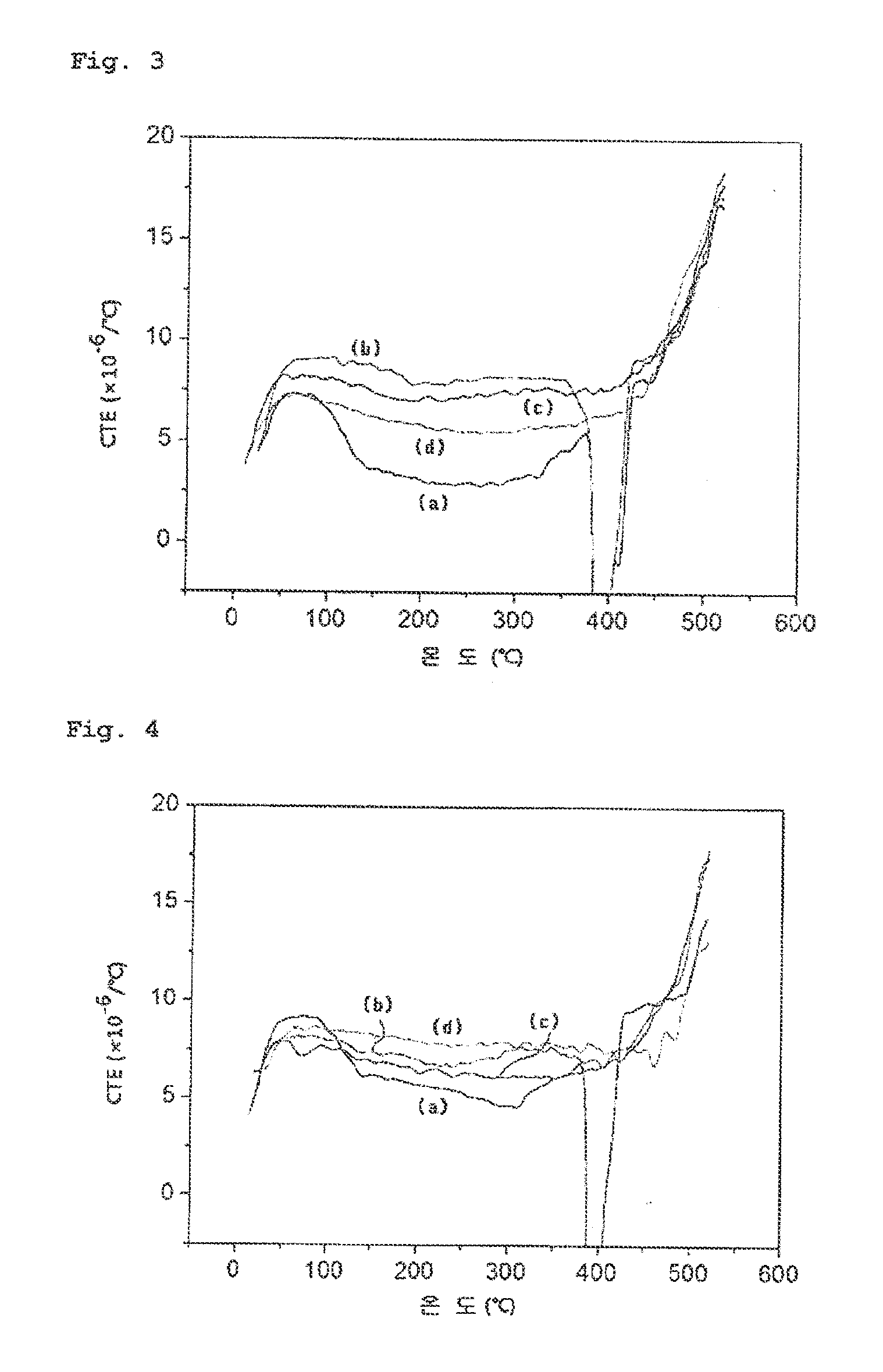
[0044]In the cases in which (a) the produced Fe—Ni substrate material was not subjected to a structure stabilization process (heat treatment), (b) it was heat-treated under a hydrogen atmosphere at 400° C. for 1 hour, (c) it was heat-treated under a hydrogen atmosphere at 500° C. for 1 hour, and (d) it was heat-treated under a hydrogen atmosphere at 600° C. for 1 hour, the thermal expansion coefficient of the Fe—Ni metal, foil substrate material as a function of the temperature of the structure stabilization process was measured by thermo-mechanical analysis (TMA), and the results of the measurement are shown in FIG. 4. As can be seen in FIG. 4, when the structure stabilization process was performed at 600° C., the average of CTEs in the temperature range (20° C. t...
example 3
[0045]An alloy metal foil substrate material composed of Fe-50 wt % Ni was produced in a manner similar to that described in Example 1 using an electrolyte solution having a composition controlled to provide Fe-50 wt % Ni.
[0046]In the cases in which (a) the produced Fe—Ni substrate material was not subjected to a structure stabilization process (heat treatment), (b) it was heat-treated under a hydrogen atmosphere at 400° C. for 1 hour, (c) it was heat-treated under a hydrogen atmosphere at 500° C. for 1 hour, and (d) it was heat-treated under a hydrogen atmosphere at 600° C. for 1 hour, the thermal expansion coefficient of the Fe—Ni metal foil substrate material as a function of the temperature of the structure stabilization process was measured by thermo-mechanical analysis (TMA), and the results of the measurement are shown in FIG. 5. As can be seen in FIG. 5, when the structure stabilization process was performed at 600° C., the average of CTEs in the temperature range (20 to 500...
PUM
| Property | Measurement | Unit |
|---|---|---|
| Temperature | aaaaa | aaaaa |
| Temperature | aaaaa | aaaaa |
| Length | aaaaa | aaaaa |
Abstract
Description
Claims
Application Information
 - R&D
- Intellectual Property
- Life Sciences
- Materials
- Tech Scout
- Unparalleled Data Quality
- Higher Quality Content
- 60% Fewer Hallucinations
Browse by: Latest US Patents, China's latest patents, Technical Efficacy Thesaurus, Application Domain, Technology Topic, Popular Technical Reports.
© 2025 PatSnap. All rights reserved.Legal|Privacy policy|Modern Slavery Act Transparency Statement|Sitemap|About US| Contact US: help@patsnap.com


