Substrate damage detection device, substrate transfer robot with substrate damage detection device, and substrate damage detection method

a technology for detecting damage to substrates and robots, which is applied in the direction of conveyor parts, transportation and packaging, instruments, etc., can solve the problems detection of damage to the substrate, and damage to the relevant portion of the substrate, so as to simplify the substrate processing system

Active Publication Date: 2016-07-12
DAIHEN CORP
View PDF10 Cites 1 Cited by
  • Summary
  • Abstract
  • Description
  • Claims
  • Application Information

AI Technical Summary

Benefits of technology

[0023]According to the present invention, the substrate damage detection device is provided at the substrate transfer robot. Thus, the substrate processing system can be simplified as compared with the conventional arrangement whereby damage detection is performed by an optical sensor provided at each chamber.
[0024]Moreover, according to an embodiment of the present invention, damage detection may be performed with respect to the entire periphery of the substrate placed on the substrate support. That is, the present invention solves the conventional problem that damage detection is possible only with respect to a part of the periphery of the substrate.

Problems solved by technology

In a substrate processing system, when a substrate transfer robot transfers a substrate between chambers such as processing chambers, damage to the substrate, such as breakage or cracking, may be made due to e.g. contact of the substrate with a chamber.
Damage to the substrate is detected based on the amount of light received by the light-receiving portion.
When a large change is observed in the level of the signal outputted from the sensors, it is determined that damage has been made to the relevant portion of the substrate.
In other words, the above-described method cannot detect damage that has been made to another pair of edges, i.e., the front and rear edges of the substrate which extend perpendicularly to the substrate introducing direction.
Moreover, in the case of a substrate having a shape other than a rectangle, i.e., a circular substrate, for example, the area for which damage detection is possible is more limited.
Thus, a relatively large number of optical sensors are necessary.

Method used


Image

  • Substrate damage detection device, substrate transfer robot with substrate damage detection device, and substrate damage detection method
  • Substrate damage detection device, substrate transfer robot with substrate damage detection device, and substrate damage detection method
  • Substrate damage detection device, substrate transfer robot with substrate damage detection device, and substrate damage detection method

Examples


Embodiment Construction

[0043]Preferred embodiments of the present invention are described below with reference to the accompanying drawings.

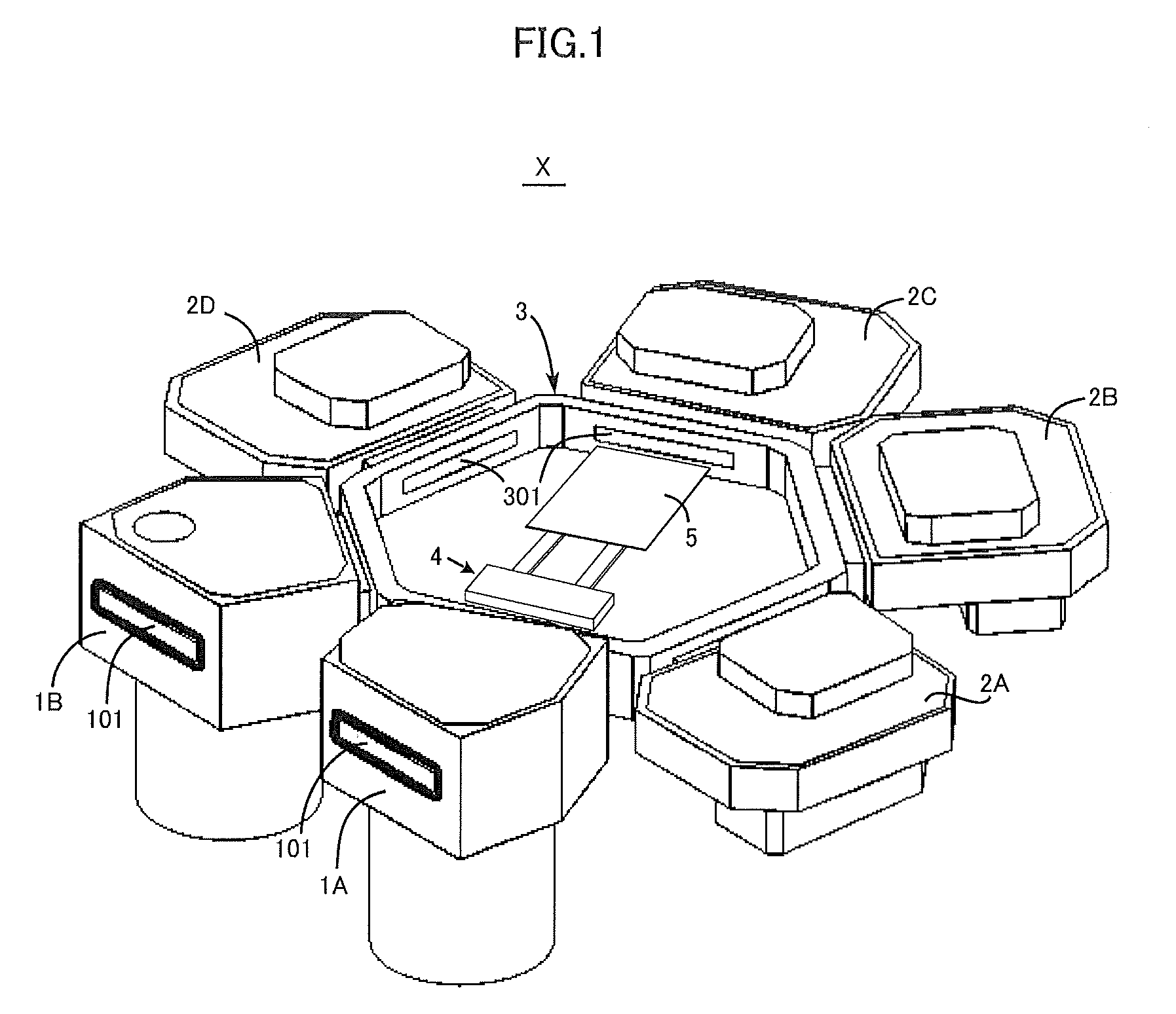
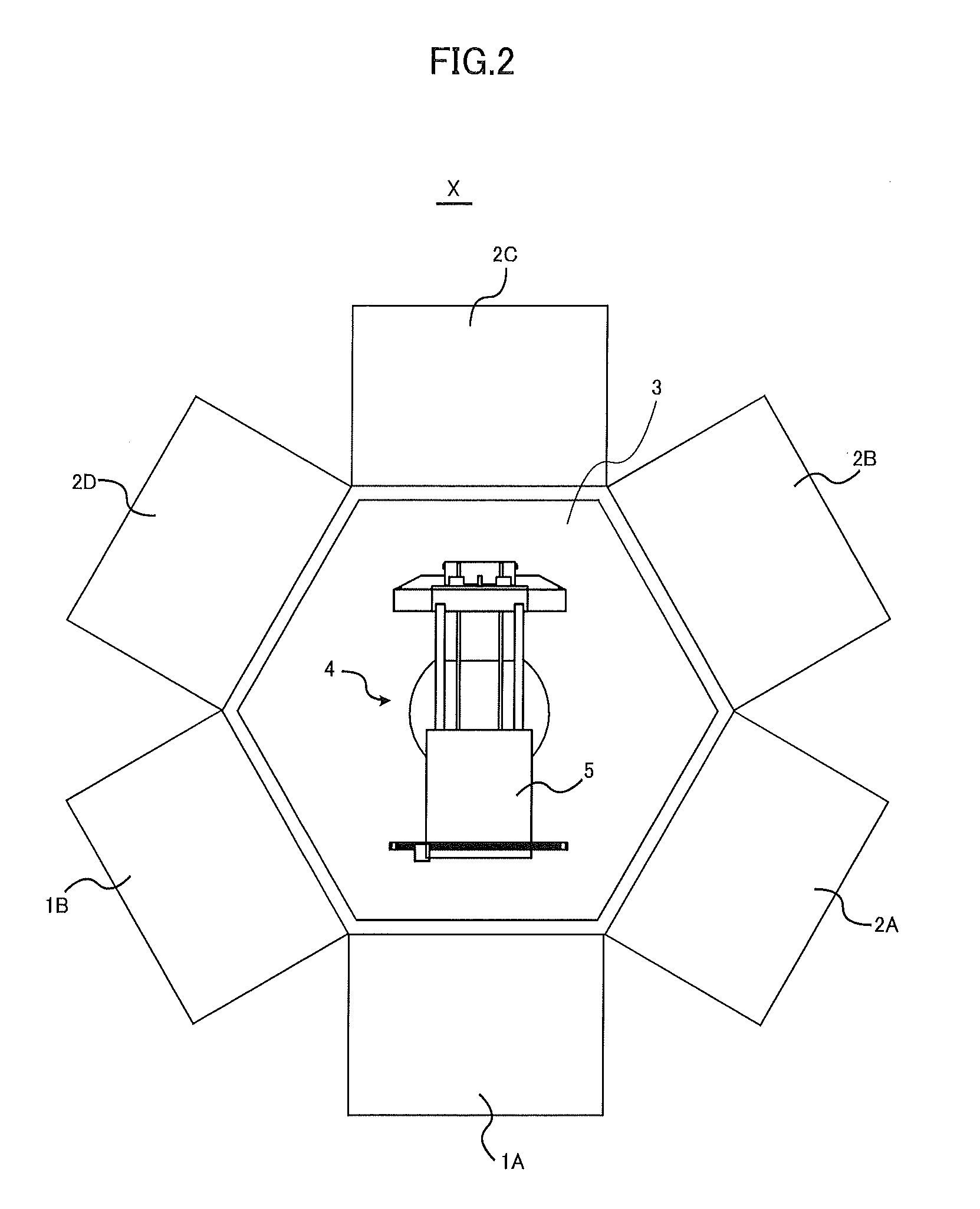
[0044]FIG. 1 is a perspective view of an example of a substrate processing system to which a substrate damage detection device according to the present invention is applicable. FIG. 2 is a top view of the substrate processing system. In FIG. 2, the chambers are illustrated as having a rectangular shape for convenience of drawing. This holds true for FIGS. 9-12.

[0045]The substrate processing system X illustrated in FIG. 1 includes two load lock chambers 1A and 1B, four processing chambers 2A, 2B, 2C and 2D, a transfer chamber 3, and a substrate transfer robot 4. The two load lock chambers 1A, 1B and the four processing chambers 2A, 2B, 2C, 2D are arranged radially around the transfer chamber 3. As illustrated in FIG. 2, the transfer chamber 3 is hexagonal as viewed in plan. The load lock chambers 1A, 1B are arranged at adjacent two of six sides of the transfer chamber ...


PUM

PropertyMeasurementUnit
movementaaaaaaaaaa
electrical structureaaaaaaaaaa
shapeaaaaaaaaaa

Abstract

A substrate damage detection device is configured to be mounted to a substrate transfer robot provided with a slidably-movable substrate support. The substrate damage detection device includes an image obtainer and a damage detector. The image obtainer, such as a camera, is configured to obtain an image of the periphery of a substrate placed on the substrate support of the transfer robot. The damage detector is configured to detect damage made to the substrate by using the image of the periphery obtained by the image obtainer.

Description

BACKGROUND OF THE INVENTION[0001]1. Field of the Invention[0002]The present invention relates to a substrate damage detection device for detecting damage made to a substrate such as a liquid crystal substrate when the substrate is being transferred by a substrate transfer robot between a plurality of processing chambers in a substrate processing system. The invention also relates to a substrate transfer robot provided with such a substrate damage detection device and to a substrate damage detection method.[0003]2. Description of the Related Art[0004]In a substrate processing system, when a substrate transfer robot transfers a substrate between chambers such as processing chambers, damage to the substrate, such as breakage or cracking, may be made due to e.g. contact of the substrate with a chamber. To remove such a damaged or defective substrate from the substrate processing system, a substrate damage detection device has conventionally been proposed that is configured to detect dam...

Claims


Application Information

Patent Timeline
Patent Type & Authority Patents(United States)
IPC IPC(8): G01N21/88H01L21/677H01L21/67G01N21/95
CPCH01L21/67742G01N21/9501H01L21/67288H01L21/67748G01N2021/9513Y10S901/47
Inventor SHIMADA, MASARUNAGANO, TAKASHIKOBAYASHI, TAKUMI
Owner DAIHEN CORP
Why Eureka
Try Eureka