Fluid-cooled battery module containing battery cells

a battery module and flue-cooled technology, applied in the field of battery modules, can solve the problems of low heat capacity, low thermal conductivity of air, unsatisfactory affecting the functioning and lifespan of a battery system,

Active Publication Date: 2014-11-20
ELECTROVAYA
View PDF1 Cites 39 Cited by
  • Summary
  • Abstract
  • Description
  • Claims
  • Application Information

AI Technical Summary

Benefits of technology

The patent describes a cooling system for battery modules that ensures uniform temperature distribution. The system uses chilled cooling fluid that flows through the module in a way that allows the fluid to reach the hottest areas first, where the cells have terminals. The cooling fluid is at its coldest when it enters the module, which results in faster heat transfer. As the fluid moves along the cooling conduit, it absorbs heat from the module, slowing down the rate of heat transfer. This leads to a more uniform temperature distribution even when the cells or the module are large and have different temperatures. The case also protects the cells from vibration and damage and provides mechanical support for each cell. It also prevents cooling fluid leakage and damage to the cells.

Problems solved by technology

Overheating or an exposure to high temperatures may undesirably affect the functioning and lifespan of a battery system.
However, air has a low thermal conductivity and a low heat capacity; thus air cooling systems exhibit inadequate efficiency for use with larger batteries.
Because aqueous fluids are most commonly used, and aqueous fluids are generally conductive, leaks in these systems can be very damaging to the battery system.
To ensure fluid-tight joining of the parts and components and to minimize susceptibility to leakage, processes and equipment used to assemble this type of cooling system are highly automated, complex, and have costs for manufacture and maintenance.
Cell temperature affects charging efficiency and capacity; lower capacity can lead to over-discharging, which will lower the operational lifespan of the cell and the battery as a whole.
A further difficulty with larger electric chemical battery cells is that different parts of the batteries themselves may have different localized temperatures.
This is the case for a number of reasons including the physical size of the cells themselves, the poor thermal conductivity within the cells themselves, and the fact that some sections of the cells may generate more heat than other sections.

Method used


Image

  • Fluid-cooled battery module containing battery cells
  • Fluid-cooled battery module containing battery cells
  • Fluid-cooled battery module containing battery cells

Examples


Embodiment Construction

[0025]Preferred embodiments of the invention and its advantages can be understood by referring to the present drawings. In the present drawings, like numerals are used for like and corresponding parts of the accompanying drawings.

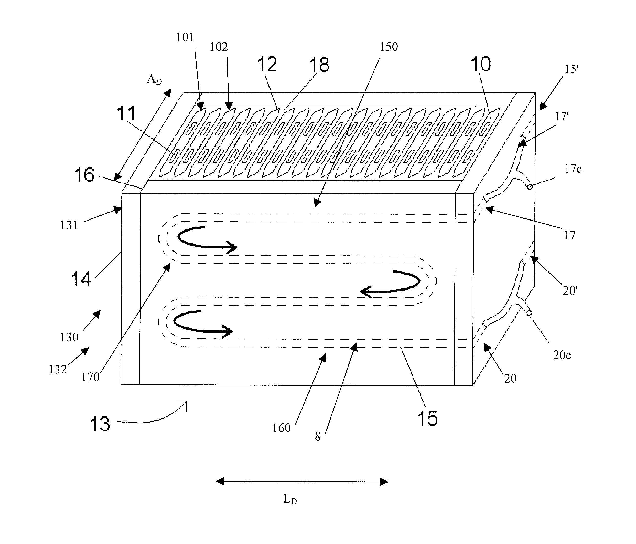
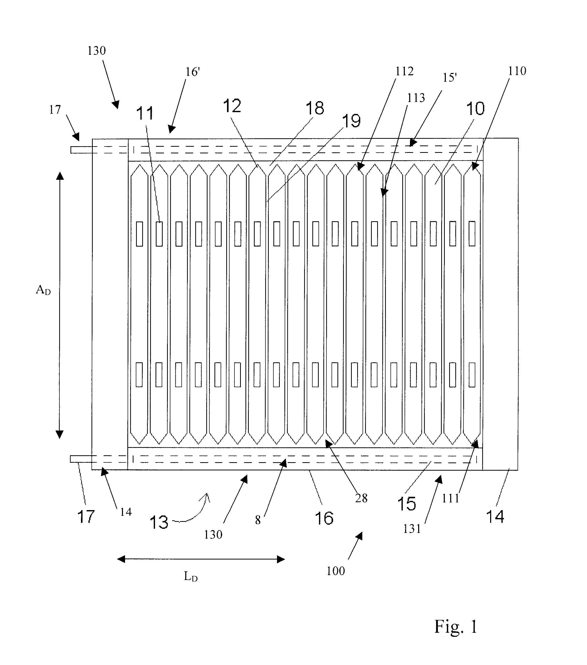
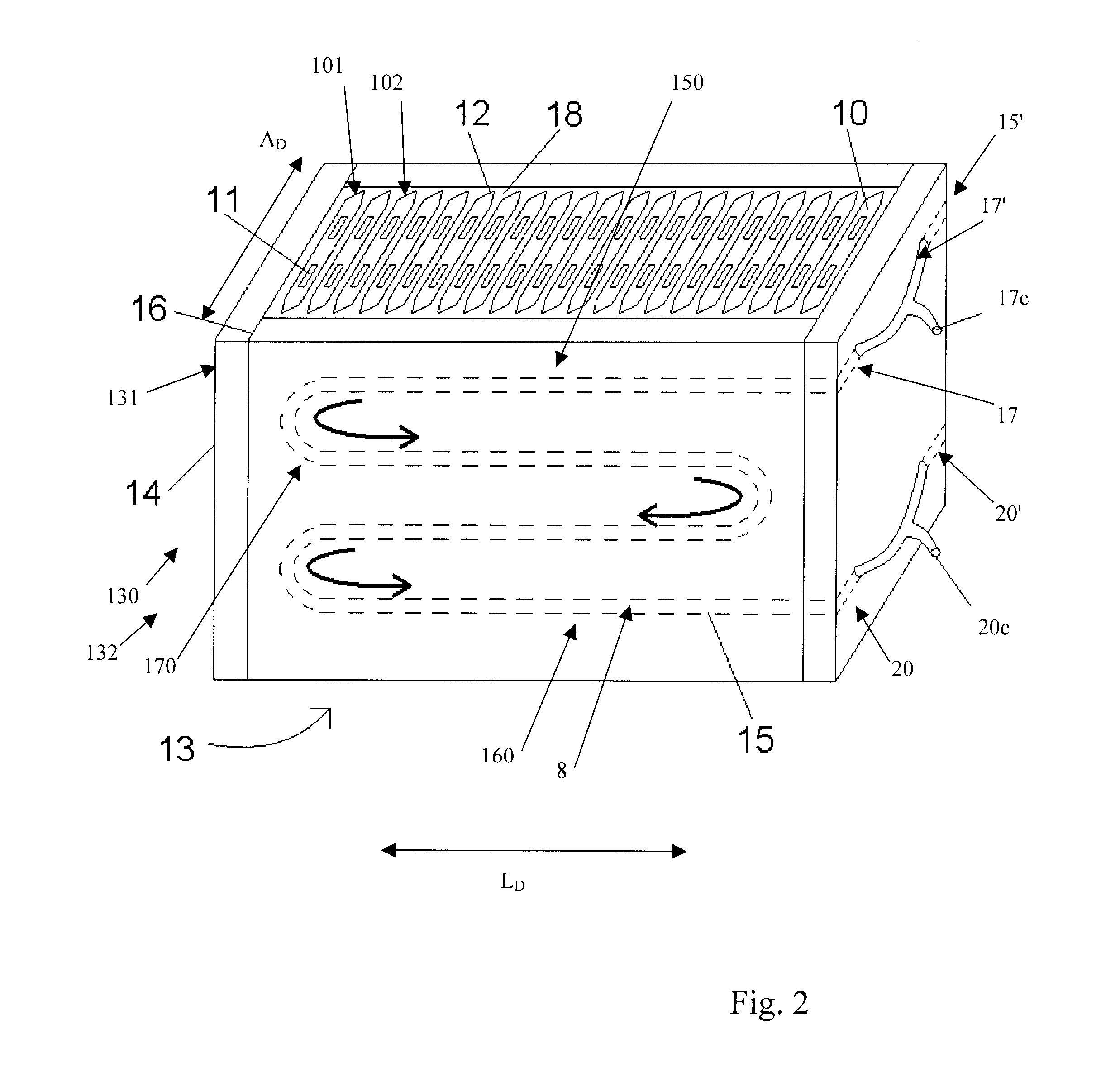
[0026]As illustrated in FIG. 1, in one embodiment of the present invention, one, and preferably a plurality of battery cells, shown generally by reference numeral 10, are contained within a battery module, shown generally by reference numeral 130. The battery module 130 preferably is formed of a battery module case 13, as shown in FIGS. 1 and 2. In a preferred embodiment, the battery module case 13 is preferably in the shape of a rectangular prism, having two longer sides along a longitudinal direction LD and two shorter sides along a lateral direction AD. The longer sides, in a preferred embodiment, are formed by cooling plates, as shown generally by reference numeral 16, and the two shorter sides in a preferred embodiment are formed by the end plates, 14....


PUM


Abstract

A battery module for receiving battery cells provides cooling through a cooling fluid. Chilled fluid travels first to the hottest part of the battery module and then continues to gradually less hot areas. As the chilled cooling fluid absorbs heat and travels to cooler parts of the battery module, the heat transfer between the fluid and the battery cells decreases because the temperature differential between the cells and cooling fluid decreases, providing a more even temperature distribution across the battery module. The cooling fluid may be contained in a conduit associated with one or more cooling plates. A plurality of slots provide a precise mechanical support for each battery cell, increasing the heat conduction from the cell to the battery module, protecting the battery module from vibration and decreasing contamination in case of thermal runaway or other damage to the cells.

Description

RELATED APPLICATIONS[0001]This application claims the benefit of 35 USC 119(e) to U.S. Provisional Application Ser. No. 61 / 631,455 filed 5 Jan. 2012 (5 Jan. 2012).FIELD OF THE INVENTION[0002]The present invention relates to battery modules for battery cells. More particularly, the present invention relates to the thermal management of battery modules.BACKGROUND OF THE INVENTION[0003]Batteries have been proposed as a clean, efficient and environmentally responsible power source for electric vehicles, and various other applications. They are also becoming more popular for large-scale energy storage, providing frequency regulation or auxiliary power to the power grid and allowing better use of intermittent power generation from sources like wind turbines and solar panels.[0004]Battery cells, and in particular, lithium ion cells, are known to generate heat when charging or discharging. Overheating or an exposure to high temperatures may undesirably affect the functioning and lifespan of...

Claims


Application Information

Patent Timeline
IPC IPC(8): H01M10/656H01M10/0525H01M10/663H01M10/653H01M10/613H01M10/647H01M50/103H01M50/209H01M50/264
CPCH01M10/5061H01M10/5004H01M10/5032H01M2220/10H01M10/504H01M10/0525H01M2220/20H01M10/5095H01M10/625H01M10/663H01M10/647H01M10/6568H01M10/6556H01M10/6555H01M10/617H01M10/613Y02E60/10H01M50/103H01M50/209H01M50/264
Inventor BHOLA, RAKESHDAS GUPTA, RAJSHEKAR
Owner ELECTROVAYA
Why Eureka
Try Eureka