
Methods and apparatus for solar energy concentration and conversion

a technology of solar energy and solar energy, applied in the direction of lighting and heating apparatus, indirect heat exchangers, instruments, etc., can solve the problems of reducing the transmission efficiency of manufactured fresnel lenses, affecting and reducing the efficiency of solar energy collection and conversion. achieve the effect of maximizing output power and high efficiency solar energy collection and conversion

Inactive Publication Date: 2014-11-06
JIN RUXIANG
View PDF0 Cites 7 Cited by
  • Summary
  • Abstract
  • Description
  • Claims
  • Application Information

AI Technical Summary

Benefits of technology

The present invention is a device that concentrates sunlight onto a small area using a curved reflector or multiple reflectors. This results in uniform solar energy collection and conversion. In one aspect, the reflector surface is segmented into smaller areas that direct sunlight to different positions on the solar cell. This maximizes output power.

Problems solved by technology

In the transmissive concentrating system using Fresnel lenses, there is a trade-off between the concentration ratio and the optical system efficiency, such that it is difficult to achieve concentrations ratios greater than 1000 without suffering efficiency loss because of the energy loss in the refractive optical components.
The transmissivity of the manufactured Fresnel lens may also degrade with extended exposure to strong solar radiation.
Since the amount of solar power collected by the dish is typically of the order of thousands of Watts, active cooling must be used to maintain a working temperature significantly less than 100 degrees Celsius in the solar cell array, possibly affecting the reliability of the HCPV system because continuous power must be applied to the cooling system, and the cooling liquid must be replenished periodically.
In a Cassagrain reflective system comprising a plurality of smaller reflectors, the cooling requirement is substantially reduced, but the system is not easily scalable, and accurate alignment of the reflectors with the prisms and the solar cells could be a challenge in controlling the system cost.
While this approach reduces overall system cost, the disadvantage is that the light pipe or prism will inevitably introduce more optical loss into the system, thereby reducing the overall system efficiency.

Method used


Image

  • Methods and apparatus for solar energy concentration and conversion
  • Methods and apparatus for solar energy concentration and conversion
  • Methods and apparatus for solar energy concentration and conversion

Examples


Embodiment Construction

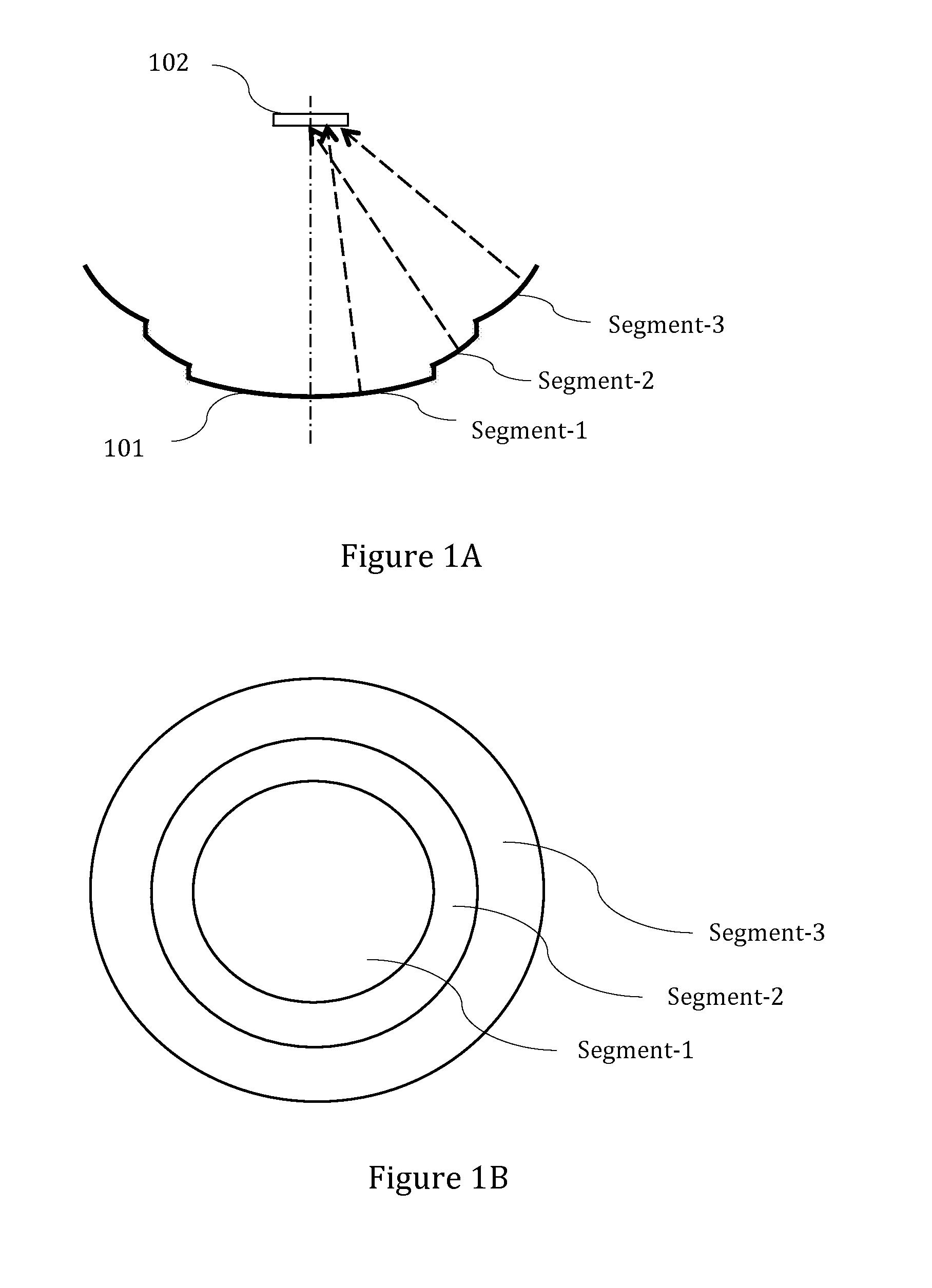
[0019]FIG. 1 shows, by way of example, a schematic representation of a reflective high concentration photovoltaic system of the present invention. In FIG. 1A, a modified parabolic reflector 101, preferably made of glass or PMMA (poly(methyl methacrylate)), directs impinging sunlight onto a solar cell 102. The dot-dashed line represents the central axis of the reflector and the solar cell, and the arrows represent the directions of the reflected solar rays.

[0020]The solar cell 102 typically comprises III-V semiconductor compounds such as layers of GaAs / InGaAs on germanium substrates. The solar cell 102 serves to absorb radiation energy over the main spectrum of the sun from ultraviolet to infrared wavelengths, and to convert solar power to electrical power with high efficiency. The solar cell 102 can be a single cell or an array of closely packaged cells. The corrugated reflector 101 is typically coated with aluminum or silver to achieve high reflectivity across a wide solar spectral...


PUM


Abstract

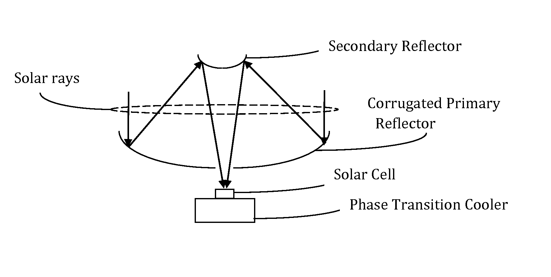
A reflective concentrating optical apparatus capable of efficient solar power collection and conversion is disclosed. A corrugated monolithic reflector or a modified Mersenne optical system with corrugated primary reflector concentrates sunlight with high irradiance uniformity and minimal optical loss, so that an optical fiber bundle or a high efficiency solar cell can be placed near the focal area for efficient light collection or solar-to-electrical power conversion. The solar cell is directly attached onto a phase-transition cooling apparatus comprising a heat pipe and a heat sink to keep the solar cell within a temperature range that enables high solar-to-electrical power conversion efficiency.

Description

CROSS-REFERENCE TO RELATED APPLICATIONS[0001]This application claims the benefit of the date of provisional patent application No. 61 / 643,386 (May 7, 2012).STATEMENT REGARDING FEDERALLY SPONSORED RESEARCH OR DEVELOPMENT (IF APPLICABLE)[0002]The invention was NOT made by an agency of the United States Government or under a contract with an agency of the United States Government.REFERENCE TO SEQUENCE LISTING, A TABLE, OR A COMPUTER PROGRAM LISTING[0003]Not applicable.COMPACT DISC APPENDIX (IF APPLICABLE)[0004]Not applicable.BACKGROUND OF THE INVENTION[0005]The present invention relates to high concentration reflective optical apparatus. In particular, the present invention relates to high concentration reflective optical systems used in solar energy collection and conversion applications that require high optical system efficiency in generating or utilizing sunlight power, photovoltaic power or solar thermal power.[0006]High concentration optical systems are widely used in various sol...

Claims


Application Information

Patent Timeline
IPC IPC(8): H01L31/052F21V8/00F24J2/10F24S23/70
CPCH01L31/0525F24J2/10G02B6/0096H01L31/0547Y02E10/40Y02E10/52H01L31/052F28D15/02F24S23/80F24S23/79
Inventor JIN, RUXIANG
Owner JIN RUXIANG
Learn More