
Microwave energy receiving board formed by secondary wavelength resonance structural units

A resonant structure and energy receiving technology, which is applied to electrical components, electromagnetic wave systems, circuit devices, etc., can solve the problems of low energy conversion efficiency and lower energy utilization rate, and achieve the effects of variable structure, light weight and simple design structure

Inactive Publication Date: 2014-04-16
ZHEJIANG UNIV
View PDF5 Cites 0 Cited by
  • Summary
  • Abstract
  • Description
  • Claims
  • Application Information

AI Technical Summary

Problems solved by technology

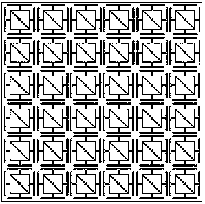
In addition, some project groups have studied rectenna arrays in an attempt to increase the received energy, but compared with the receiving efficiency of unit antennas, the overall energy conversion efficiency is lower, and due to consideration of size and volume factors, rectenna arrays are required to be designed more compactly. However, due to the coupling between ordinary antenna elements, the distance between the array elements is at least half a wavelength, which greatly reduces the energy utilization rate.

Method used


Image

  • Microwave energy receiving board formed by secondary wavelength resonance structural units
  • Microwave energy receiving board formed by secondary wavelength resonance structural units
  • Microwave energy receiving board formed by secondary wavelength resonance structural units

Examples


Embodiment Construction

[0022] The present invention will be further described below in conjunction with the accompanying drawings and specific embodiments.

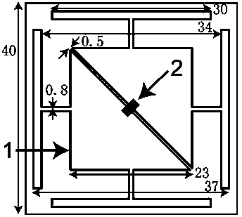
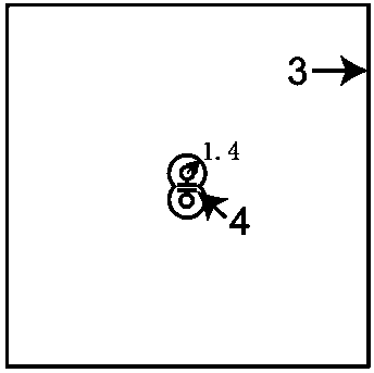
[0023] Such as figure 1 , figure 2 As shown, each sub-wavelength resonant unit is composed of three layers and has a square structure. A layer of square metal copper sheet 1 is plated in the middle of the Rogers circuit board on the middle layer. The square metal copper sheet 1 is composed of two isosceles right triangles. Both sides of the two isosceles right-angled triangle gaps are respectively connected to the two input interfaces of the high-frequency rectification chip 2, and as the input end of the high-frequency rectification circuit, the four sides of the square metal copper sheet 1 are respectively connected to the respective The strip-shaped metal copper sheet is connected, and each strip-shaped metal copper sheet is parallel to the four sides of the square respectively, and a layer of metal copper sheet bottom plate 3 is plated un...


PUM


Abstract

The invention discloses a high efficient microwave energy receiving board formed by secondary wavelength resonance structural units. Each of the unit is in a square structure. A layer of square sheet copper is plated in the middle of a Rogers circuit board of an intermediate layer; the sheet copper is formed by two right-angle isosceles triangles. Two sides of a slit between the two right-angle isosceles triangles are respectively connected with two input interfaces of a high frequency rectification chip and are used as input terminals of a high frequency rectification circuit; and four sides of the square sheet copper are respectively connected with their own long-strip sheet coppers respectively through strip-shaped sheet coppers. A layer of sheet base plate is fully plated under the circuit board of the intermediate layer; two crossed annular openings are opened in the middle of the sheet base plate; two small sheet coppers in the middle of the two annular openings pass through through holes of the circuit board and are respectively connected with two output terminals of the high frequency rectification chip; and a high frequency filtering capacitor is in parallel connection between the two sheet coppers. According to the invention, super high efficient receiving and conversion of microwave energy can be realized; the costs are low and the structure is simple; and efficiencies of receiving and conversion of energy are high; and therefore, the high efficient microwave energy receiving board can be widely applied to microwave energy transmission of various frequency ranges as well as research and development and application fields of receiving equipment.

Description

technical field [0001] The invention relates to a microwave energy receiving board, in particular to a microwave energy receiving board composed of sub-wavelength resonant structural units. Background technique [0002] Microwave energy transmission technology refers to a non-contact energy transmission technology that uses free space as the propagation medium to directly transmit energy from the transmitting end to the receiving end. Since the transmission efficiency of microwave energy transmission technology in the S and C bands is generally above 90%, Moreover, the intensity and direction of microwave beams are easier to control, making microwave energy transmission technology receive more and more attention internationally and domestically. Especially in recent years, it has been fully developed. There are broad application prospects. [0003] Since Tesla's experiments at the end of the seventeenth century verified Hertz's theory of radio energy transmission, modern mi...

Claims


Application Information

Patent Timeline
Patent Type & Authority Patents(China)
IPC IPC(8): H02J17/00H02J50/20
Inventor 叶德信王静雨彭政谕张斌皇甫江涛冉立新
Owner ZHEJIANG UNIV
Learn More