Solar cell and preparing method of the same
a solar cell and a technology of solar cells, applied in the field of solar cells and a method of preparing the same, can solve the problems of increasing the interest in new renewable energy and the need for new renewable energy, and achieve the effects of preventing the increase of the series resistance rs caused by the contact resistance layer, superior reactivity, and reducing the cost of production
- Summary
- Abstract
- Description
- Claims
- Application Information
AI Technical Summary
Benefits of technology
Problems solved by technology
Method used
Image

Examples
first embodiment
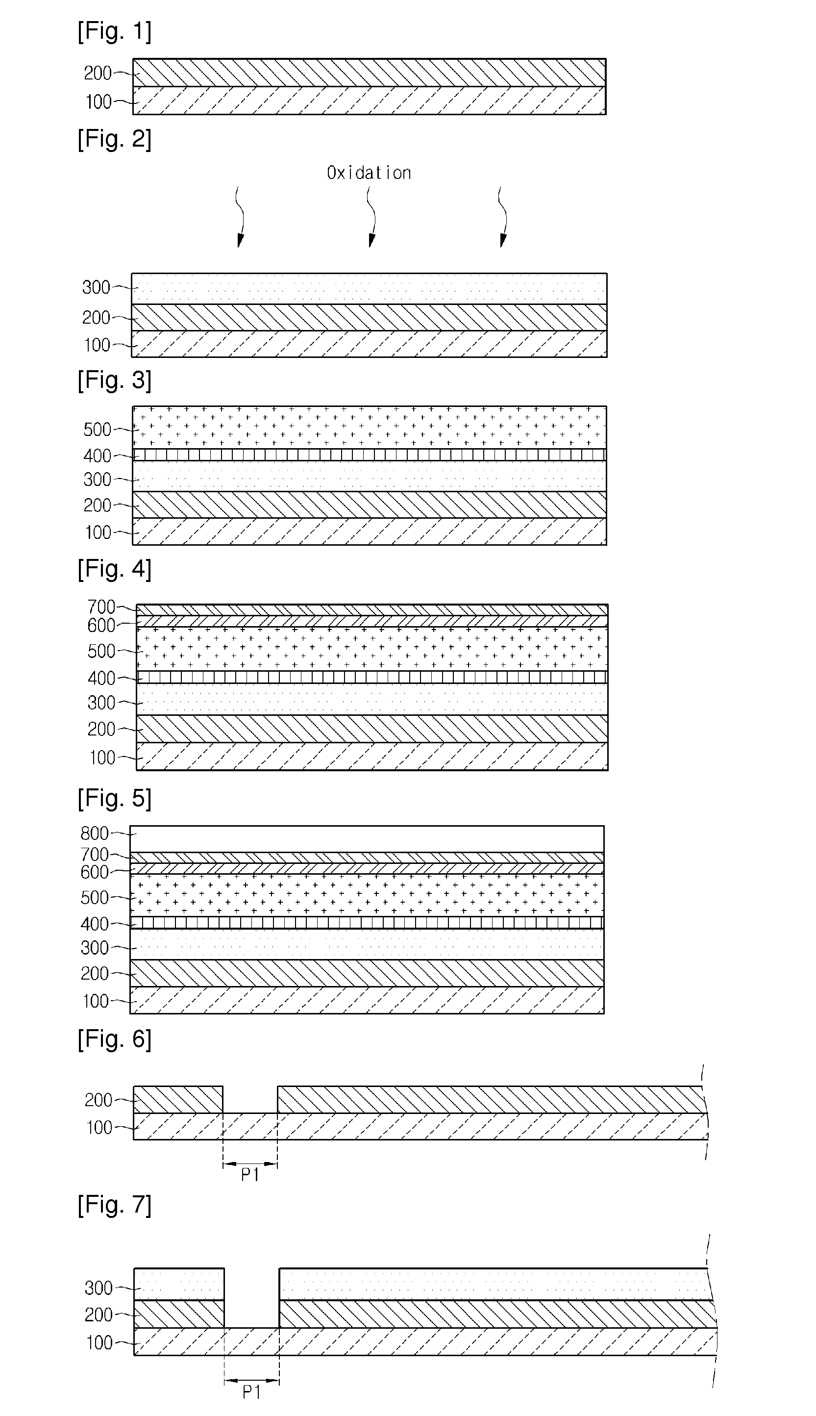
[0015]FIGS. 1 to 5 are sectional views showing a method of fabrication a solar cell according to the
[0016]Referring to FIG. 1, a back electrode layer 200 is formed on a support substrate 100. The back electrode layer 200 may be formed through a PVD (Physical Vapor Deposition) scheme or a plating scheme.
[0017]The support substrate 100 has a plate shape and supports the back electrode layer 200, a molybdenum oxide layer 300, a contact resistance layer 400, a light absorbing layer 500, a buffer layer 600, a high-resistance buffer layer 700, and a front electrode layer 800. The support substrate 100 may be transparent, and may be rigid or flexible.
[0018]he support substrate 100 may include an insulator. For example, the support substrate 100 may include a glass substrate, a plastic substrate, or a metallic substrate. In more detail, the support substrate 100 may include a soda lime glass substrate. In addition, the support substrate 100 may include a ceramic substrate including alumina,...
second embodiment
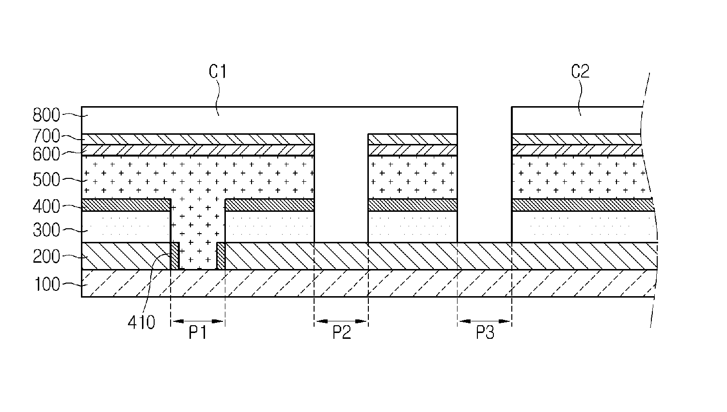
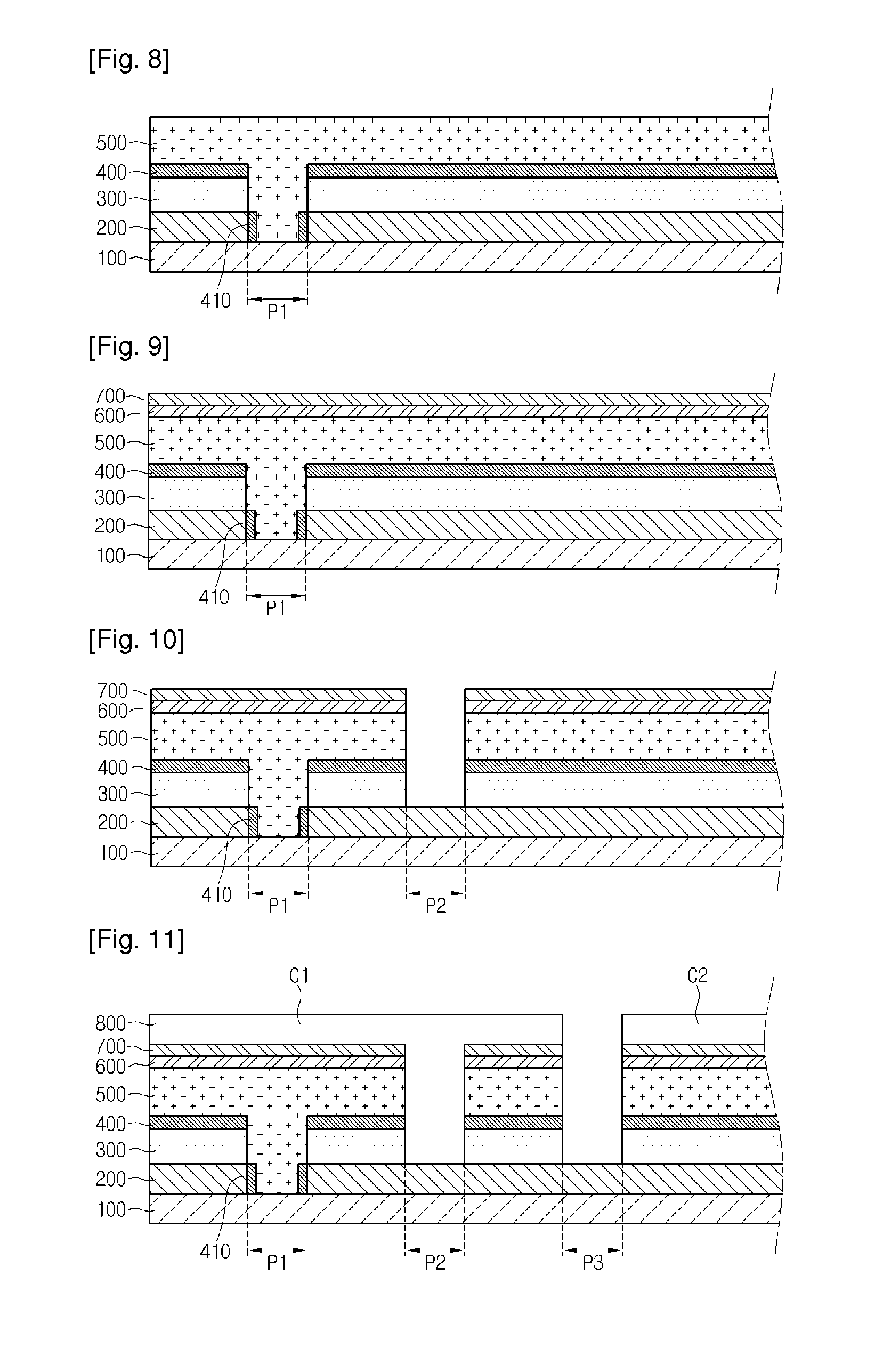
[0037]FIGS. 6 to 11 are sectional views showing a method of fabrication a solar cell according to the
[0038]Referring to FIG. 6, a back electrode layer material is coated on the support substrate 100 and a first perforating hole P1 for separating the back electrode layer material is formed. That is, the back electrode layer 200 includes the first perforating hole P1, and both sides of the back electrode layer 200 may be exposed by the first perforating hole P1. A top surface of the support substrate 100 may be partially exposed by the first perforating hole P1. The back electrode layer 200 may be divided into a plurality of back electrodes through the first perforating hole P1.
[0039]Referring to FIG. 7, the molybdenum oxide layer 300 is formed on the back electrode layer 200. When oxidizing a back electrode after making the perforating hole, an oxide layer may be formed on a sidewall of the perforating hole as well as the top surface of the back electrode layer 200.
[0040]Referring to...
PUM
 Abstract
Description
Claims
Application Information
 - R&D
- Intellectual Property
- Life Sciences
- Materials
- Tech Scout
- Unparalleled Data Quality
- Higher Quality Content
- 60% Fewer Hallucinations
Browse by: Latest US Patents, China's latest patents, Technical Efficacy Thesaurus, Application Domain, Technology Topic, Popular Technical Reports.
© 2025 PatSnap. All rights reserved.Legal|Privacy policy|Modern Slavery Act Transparency Statement|Sitemap|About US| Contact US: help@patsnap.com