
Method for manufacturing electrode for storage battery

a technology for storage batteries and manufacturing methods, which is applied in the manufacture of batteries, cell components, final products, etc., can solve the problems of reducing the potential or reducing the material in the electrode, and reducing the discharge capacity of the battery, so as to achieve high density and high capacity

Active Publication Date: 2014-10-02
SEMICON ENERGY LAB CO LTD
View PDF11 Cites 29 Cited by
  • Summary
  • Abstract
  • Description
  • Claims
  • Application Information

AI Technical Summary

Benefits of technology

The patent text describes using a conductive additive called acetylene black in batteries to improve contact between the active material and the conductive additive, which can be a high-volume particle. However, this conductive additive can make direct contact with the active material, resulting in high contact resistance. Additionally, increasing the amount of conductive additive can decrease the percentage of active material in the battery and lower its capacity. The patent also discusses using multilayer graphene with a longer interlayer distance between graphene layers, which allows carrier ions to easily transfer between layers and increases the battery's capacity per unit volume. Overall, the patent aims to provide an electrode for a storage battery with a high-density active material layer that contains a smaller percentage of conductive additive and uses multilayer graphene to improve the battery's performance.

Problems solved by technology

Further, if the amount of the conductive additive is increased to increase contact points between the active material and the conductive additive, the percentage of the amount of the active material in the electrode decreases, resulting in the lower discharge capacity of the battery.
In this case, iron, lead, copper, or the like contained as an impurity in a graphite particle reacts with the active material or the current collector, which might reduce the potential or capacity of the battery.
Further, as particles of the active material become minuter, cohesion between the particles becomes stronger, which makes uniform dispersion in the binder or the conductive additive difficult.

Method used


Image

  • Method for manufacturing electrode for storage battery
  • Method for manufacturing electrode for storage battery
  • Method for manufacturing electrode for storage battery

Examples


embodiment 1

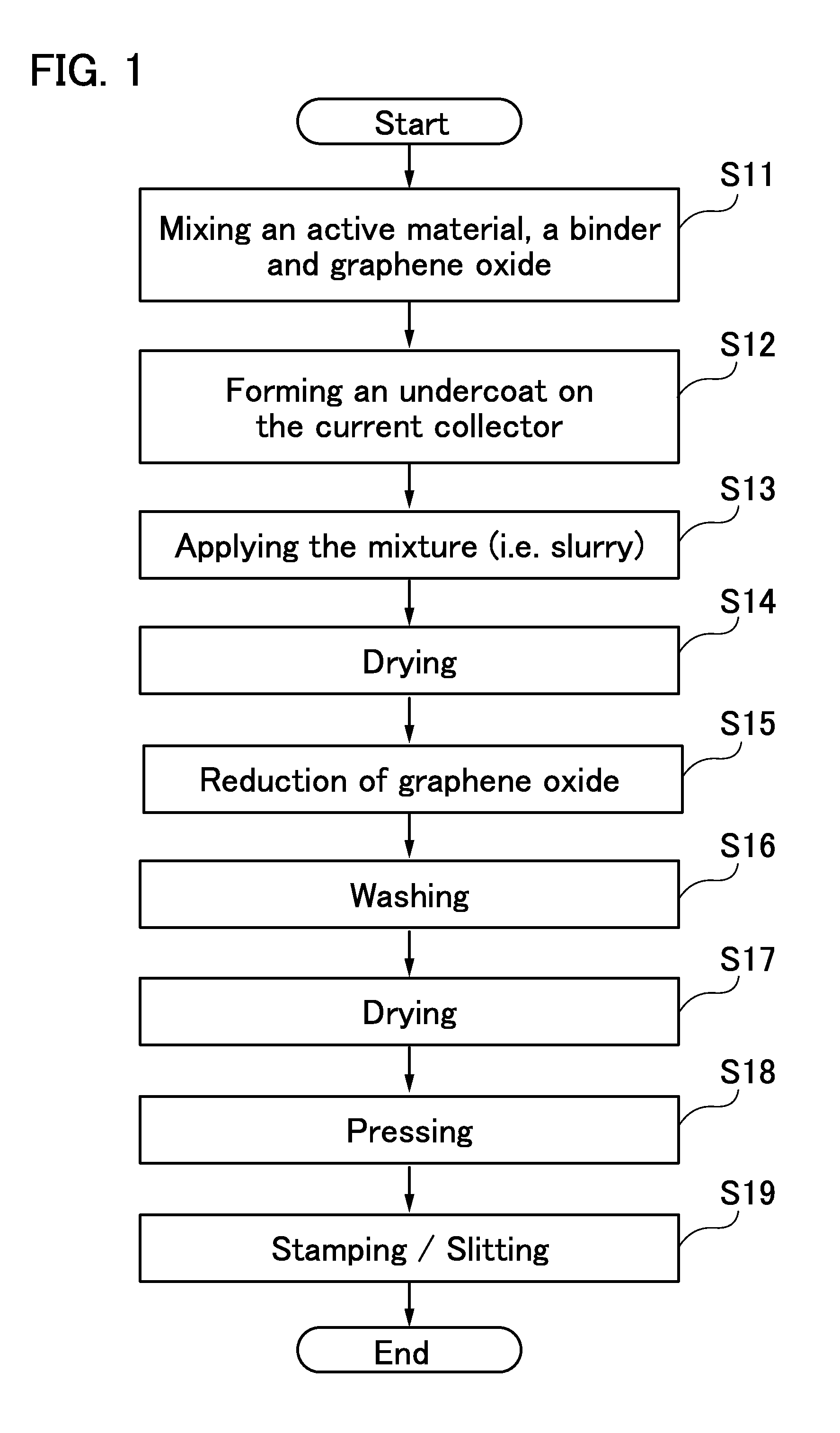
[0039]In this embodiment, a method for forming an electrode for a storage battery of one embodiment of the present invention will be described with reference to FIG. 1.

[0040]First, a description will be given of the significance of forming graphene in an electrode for a storage battery by reducing graphene oxide. Then, a method for forming an electrode for a storage battery using graphene oxide will be described.

[0041]An electrode for a storage battery of one embodiment of the present invention includes graphene as a conductive additive. However, in the case where an electrode for a storage battery is formed in such a manner that graphene or graphene formed by reducing graphene oxide in advance (reduced graphene oxide; RGO) are mixed with an active material and a binder, graphene flakes or RGO flakes aggregate in the electrode because of its low dispersibility and thus it is difficult to achieve favorable battery characteristics.

[0042]On the other hand, in the case of using graphene...

embodiment 2

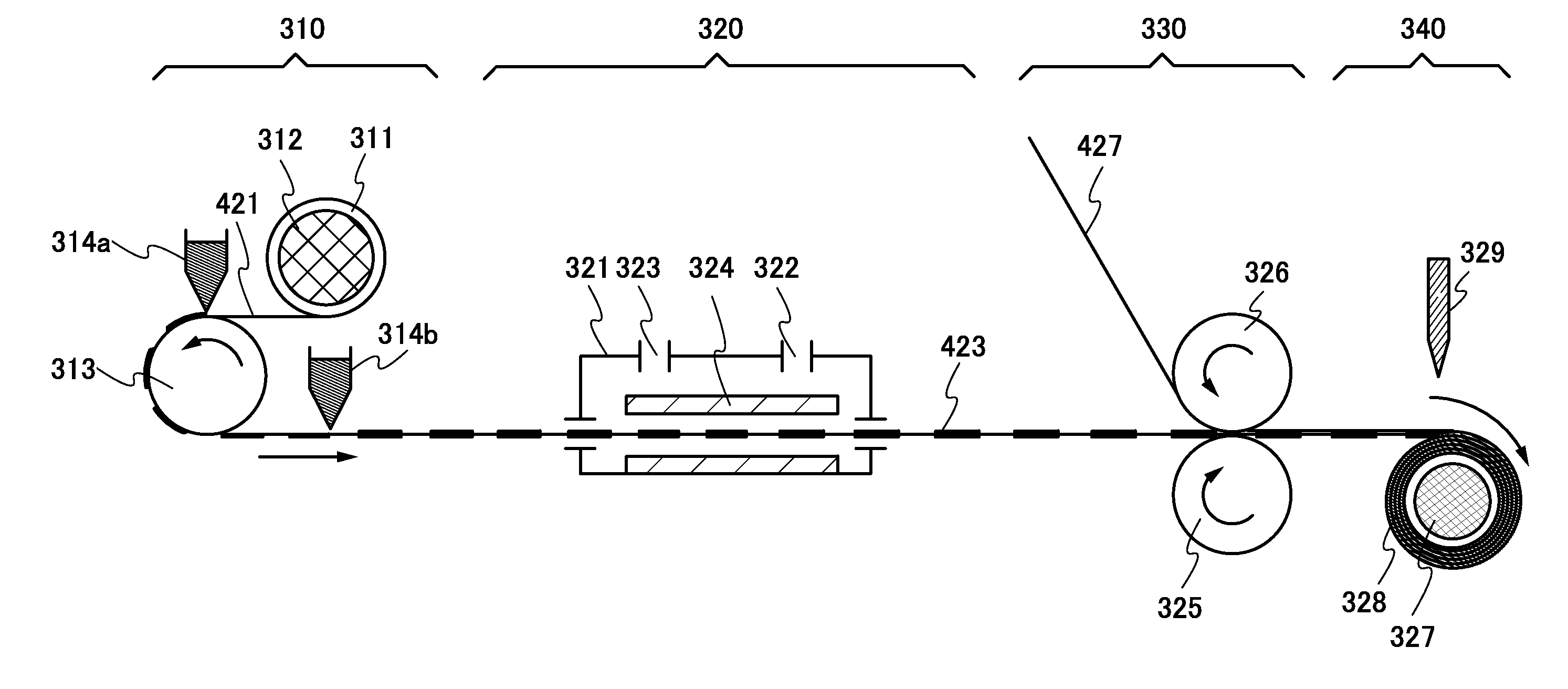
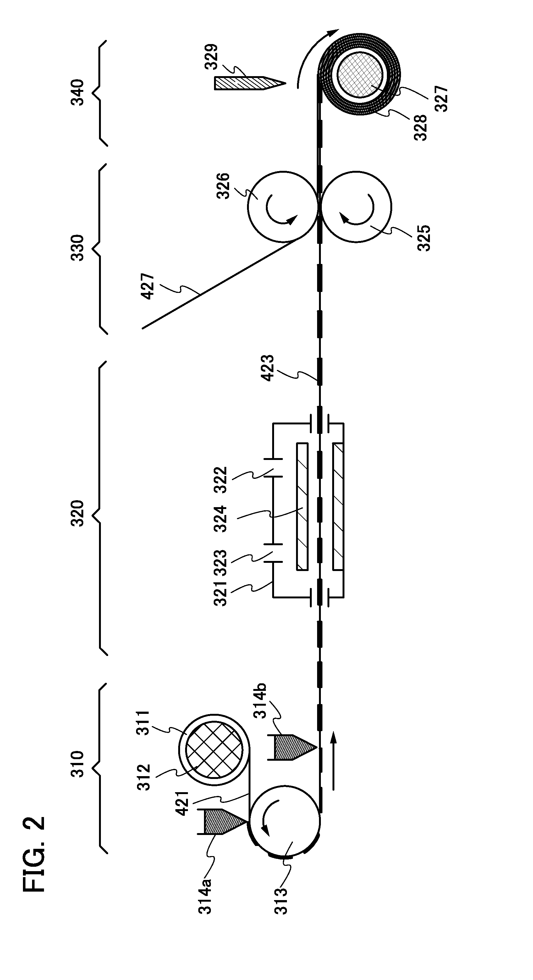
[0088]In this embodiment, the case of employing the method for forming an electrode for a storage battery that is described in Embodiment 1 for mass production will be described with reference to FIG. 2 and FIGS. 3A to 3C.

[0089]It is preferable to successively perform steps to complete a storage battery electrode from a step of applying a slurry to a substrate, with the use of a fabricating apparatus such as a roll-to-roll apparatus, in the method for forming a storage battery electrode in Embodiment 1. In the case of successively perform the steps with the use of a fabricating apparatus such as a roll-to-roll apparatus, however, a change in the concentration of a reducing solution with time in a reduction step of graphene oxide causes variation in the reduction amount of graphene oxide in storage battery electrodes, resulting in uneven characteristics of the storage battery electrodes.

[0090]Preventing a change in the concentration of a reducing solution requires a control mechanism...

embodiment 3

[0127]In this embodiment, a battery cell and a fabricating method thereof will be described with reference to FIGS. 6A to 6C, FIGS. 7A to 7C, and FIGS. 8A to 8C.

[0128]First, the structure of a battery cell will be described. The storage battery electrode of one embodiment of the present invention can be used as either or both of a positive electrode and a negative electrode.

[0129]First, a positive electrode that can be used for a battery cell will be described with reference to FIGS. 6A to 6C.

[0130]FIG. 6A is a perspective view of a positive electrode 400, and FIG. 6B is a cross-sectional view of the positive electrode 400. The positive electrode 400 includes a positive electrode current collector 401 and a positive electrode active material layer 402 formed over the positive electrode current collector 401 by a coating method, a CVD method, a sputtering method, or the like, for example. Further, an undercoat 403 is provided between the positive electrode current collector 401 and t...


PUM

PropertyMeasurementUnit
Boiling pointaaaaaaaaaa

Abstract

To provide a storage battery electrode including an active material layer with high density that contains a smaller percentage of conductive additive. To provide a storage battery having a higher capacity per unit volume of an electrode with the use of the electrode for a storage battery. A slurry that contains an active material and graphene oxide is applied to a current collector and dried to form an active material layer over the current collector, the active material layer over the current collector is rolled up together with a spacer, and a rolled electrode which includes the spacer are immersed in a reducing solution so that graphene oxide is reduced.

Description

BACKGROUND OF THE INVENTION[0001]1. Field of the Invention[0002]The present invention relates to an electrode for a storage battery and a method for manufacturing the electrode for a storage battery.[0003]2. Description of the Related Art[0004]With the recent rapid spread of portable electronic devices such as mobile phones, smartphones, electronic books, and portable game machines, secondary batteries for drive power supply have been increasingly required to be smaller and to have higher capacity. Storage batteries typified by lithium-ion secondary batteries, which have advantages such as high energy density and high capacity, have been widely used as secondary batteries used for portable electronic devices.[0005]A lithium-ion secondary battery, which is one of storage batteries and widely used due to its high energy density, includes a positive electrode including an active material such as lithium cobalt oxide (LiCoO2) or lithium iron phosphate (LiFePO4), a negative electrode for...

Claims


Application Information

Patent Timeline
IPC IPC(8): H01M4/04H01M4/139
CPCH01M4/049H01M4/0404H01M4/0435H01M4/139H01M4/625Y02E60/10Y02P70/50H01M10/0525B32B3/30B32B5/022B32B15/08B32B15/12B32B15/14B32B21/06B32B27/00B32B37/10B32B37/144B32B37/24B32B2037/243B32B2255/06B32B2255/20B32B2305/02B32B2305/20B32B2307/202B32B2307/206B32B2317/12B32B2457/10H01M4/0471H01M2220/30
Inventor NANBA, KENRYOYUKAWA, MIKIO
Owner SEMICON ENERGY LAB CO LTD
Learn More