
Method of manufacturing graphene using metal catalyst

a metal catalyst and graphene technology, applied in the direction of catalyst activation/preparation, metal/metal-oxide/metal-hydroxide catalysts, physical/chemical process catalysts, etc., can solve the problem of low graphene growth rate, multilayer graphene is present as islands, epitaxial graphene layer or epitaxial graphene layer is not easily grown, etc. problem, to achieve the effect of increasing the growth rate of graphen

Active Publication Date: 2014-10-02
SRC INC
View PDF5 Cites 21 Cited by
  • Summary
  • Abstract
  • Description
  • Claims
  • Application Information

AI Technical Summary

Benefits of technology

The present invention relates to a method for growing graphene on a metal catalyst in a unidirectional orientation. This method allows for the epitaxial growth of graphene, resulting in the formation of high-quality, monolayer graphene with a high growth rate. This has technical applications in the production of graphene-based electronic devices and materials.

Problems solved by technology

In the prior art, the use of general copper foils suffers from a problem in that multilayer graphene is present as islands or an epitaxial graphene layer or epitaxial graphene layers do not easily grow.
Particularly, when a metal has low solubility or low reactivity with the element to be adsorbed, it barely acts as a catalyst.
Due to this low reactivity, it is very difficult to control the adsorption of carbon atoms during the CVD processes.
If structures having different orientations are present together, the energy state will become non-uniform, and thus the adsorption rate of carbon will differ between areas.
This problem results in the growth of multilayer graphene in some areas to form graphite.
However, the results of the studies did not lead to industrialization, because only single crystalline metals having a size of several tens of nm can be prepared and it is impossible to obtain large areas which are industrially applicable.
In addition, for industrial application, graphene is required to be formed uniformly as single layers, but the use of general copper foils in the prior art suffers from a problem in that multilayer graphene is present as islands, because the epitaxial growth rate of graphene is low.

Method used


Image

  • Method of manufacturing graphene using metal catalyst
  • Method of manufacturing graphene using metal catalyst
  • Method of manufacturing graphene using metal catalyst

Examples


example 1

Fabrication of Graphene Thin Film on Rolled Copper Foil

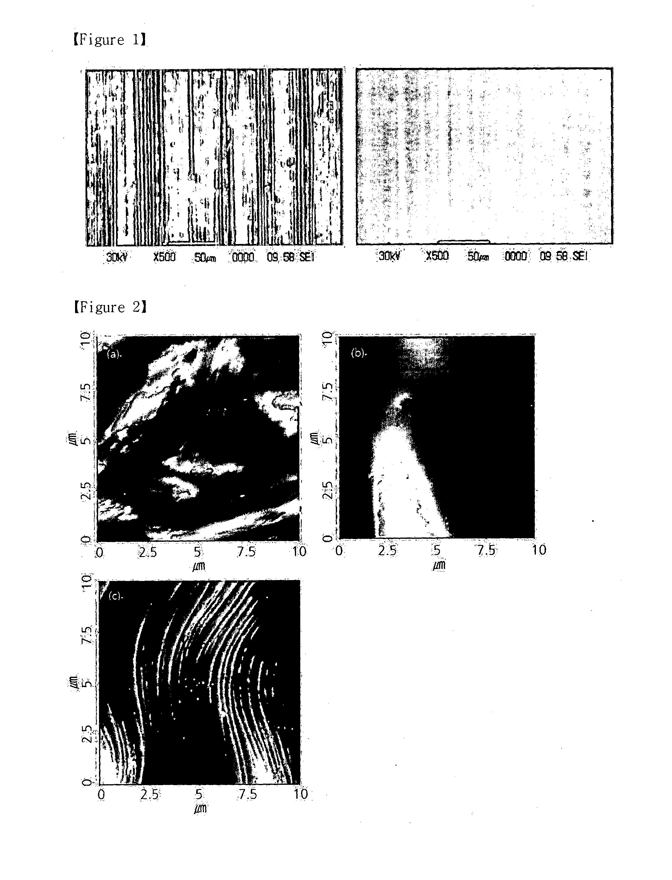
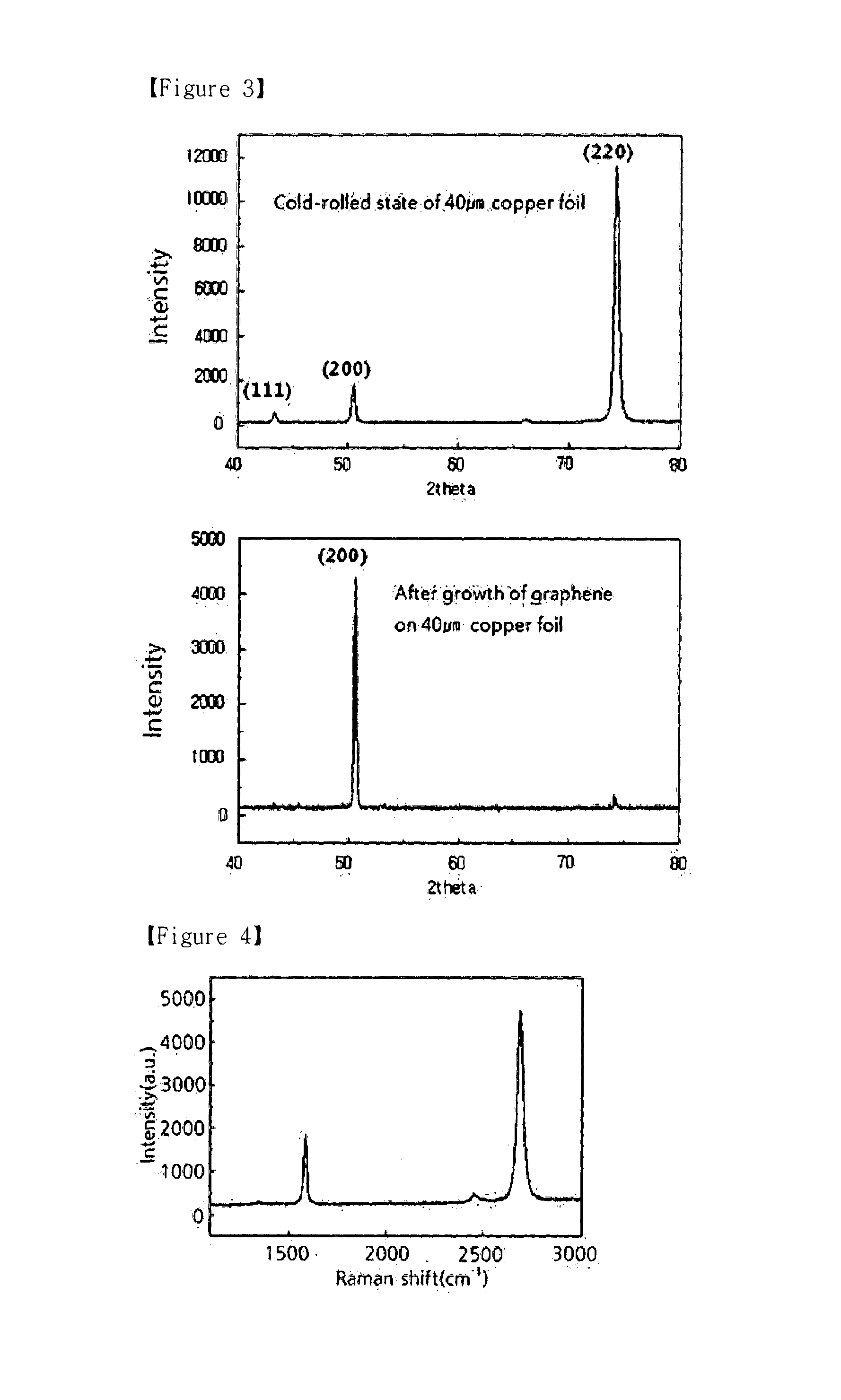
[0041]Tough pitch copper foils (a purity of 99.9% or more, an oxygen content of 0.05% or less) having thicknesses of 0.5 mm and 0.2 mm were annealed, and then cold-rolled to thicknesses of 12 μm, 25 μm, 40 μm, 50 μm and 100 μm. The cold-rolled foils were heated at various annealing temperatures so that 95% or more thereof was oriented in the (100) direction. It was confirmed that a graphene thin film was evenly formed on the annealed foils (see FIG. 1). After recrystallization, only crystal growth occurred on the foils, and thus the orientation of the foils did not change to a new orientation. Table 1 below shows the results of forming graphene layer at various reduction ratios under various heat treatment conditions.

TABLE 1ThicknessThicknessRecrystallizationFormationof rawafterannealingofmaterialrollingReduction(100) planetemperaturemonolayer(mm)(μm)ratio (%)orientation(° C.)graphenePreparation0.21294◯200◯Example 1Preparation0....

example 2

Fabrication of Graphene Layer on Electrodeposited Copper Plated Tough Pitch Copper Foil

[0045]2-1: Fabrication of Electrodeposited Copper Foil by Pulse-Current Plating and Graphene Layer

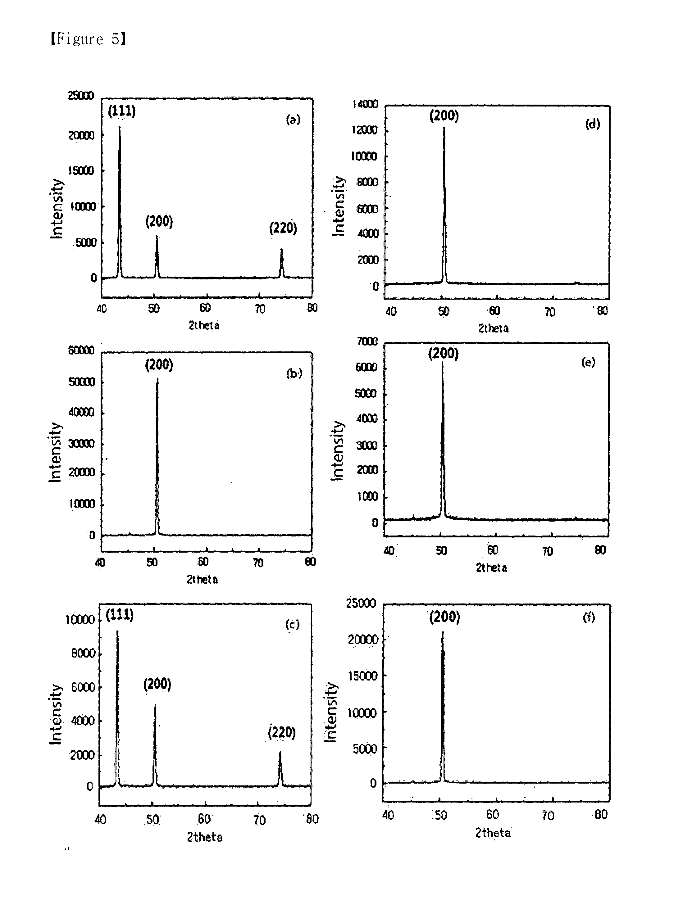
[0046]Plain tough pitch copper foils were air-stirred in a solution composed of 180-330 g / L of copper sulfate pentahydride (CuSO4.5H2O), 40-120 g / L of sulfuric acid and 40-120 ppm of hydrochloric acid at a temperature of 30-55° C. and a current density of 1-10 A / dm2, thereby pulse current plating the foils. The results are shown in FIG. 5, and the pulse waveform is expressed as current supply time: rest time.

[0047]FIGS. 5(a) and 5(b) show the results of measuring the state of a specimen obtained by plating copper on a copper foil at a ratio of 80:20 at a current density of 4.2-4.3 A / dm2 and the orientation of a structure obtained by growing graphene on the specimen at 1000° C.; FIGS. 5(c) and 5(d) show the results of measuring the state of a specimen obtained by plating copper on a copper foil at a ra...

example 3

Formation of Graphene on Copper Alloy Catalyst Substrate

[0054]A copper alloy foil containing 140 ppm of silver (see FIG. 9(b)) was heated at 600° C. for 30 minutes in an atmosphere of 70 sccm methane and 10 sccm hydrogen, and whether graphene was formed on the alloy foil was examined. As a control, copper (see FIG. 9(a)) was treated under the same conditions, and whether graphene was formed thereon was examined (see FIG. 9).

[0055]It can be seen that, when graphene was formed on copper, graphene islands and carbides were formed, but on the silver-containing copper alloy, graphene was epitaxially formed. However, when copper was previously annealed at 800° C. to form steps, graphene was epitaxially formed thereon.

[0056]The above copper alloy and copper had a hexagonal lattice structures having the (111) or (100) orientation after annealing, and these catalyst substrates also had the same orientation in the following examples.

[0057]Thus, it could be seen that the addition of a substitu...


PUM

PropertyMeasurementUnit
thicknessaaaaaaaaaa
temperatureaaaaaaaaaa
current densityaaaaaaaaaa

Abstract

The present invention relates to a method for producing graphene on a face-centered cubic metal catalyst having a plane oriented in one direction, and more particularly to a method of producing graphene on a metal catalyst having the (100) or (111) crystal structure and a method of producing graphene using a catalyst metal foil having a single orientation, obtained by electroplating a metal catalyst by a pulse wave current and annealing the metal catalyst. The invention also relates to a method of producing graphene using a metal catalyst, and more particularly to a method of producing graphene, comprising the steps of: alloying a metal catalyst with an alloying element; forming step structures on the metal catalyst substrate in an atmosphere of a gas having a molecular weight of carbon; and supplying hydrocarbon and hydrogen gases to the substrate. On unidirectionally oriented metal catalyst prepared according to the present invention, graphene can be grown uniformly and epitaxially. Moreover, a method for producing graphene according to the present invention can form monolayer graphene by epitaxially growing graphene while increasing the growth rate of graphene.

Description

TECHNICAL FIELD[0001]The present invention relates to a method of producing graphene using a metal catalyst.BACKGROUND ART[0002]Graphene is attracting a great deal of attention because of its excellent properties. With respect to graphene, professors Geim and Novoselov at the University of Manchester first succeeded in separating atomic layers from graphite using scotch tape in the year 2004 and were awarded the Nobel Prize for their discovery of graphene in the year 2010. In the year 2010, a roll-to-roll transfer technique of manufacturing large-area graphene having an area of 30 inches was reported, and technologies enabling graphene to be industrially applied have been continuously developed. For industrial application, graphene is required to be formed uniformly as a single layer. In the prior art, the use of general copper foils suffers from a problem in that multilayer graphene is present as islands or an epitaxial graphene layer or epitaxial graphene layers do not easily grow...

Claims


Application Information

Patent Timeline
Patent Type & Authority Applications(United States)
IPC IPC(8): C01B31/04
CPCB01J23/72C23C16/26C01B31/0453C23C16/0218C23C16/0281C01B31/0461B01J37/348B01J23/50B01J23/52B01J23/8926B01J35/002B01J37/18B82Y30/00B82Y40/00C01B32/186C01B32/188B01J35/30
Inventor KIM, KANG HYUNGMAENG, KWAN SUBPARK, CHOL WOOCHA, SE WONHONG, SE YOUNHONG, BYUNG HEEJUNG, MYUNG HEEKIM, KYUNG EUNPARK, SU BEOM
Owner SRC INC
Learn More