Mass Spectrometers Comprising Accelerator Devices

Active Publication Date: 2014-09-25
MICROMASS UK LTD
View PDF2 Cites 8 Cited by
  • Summary
  • Abstract
  • Description
  • Claims
  • Application Information

AI Technical Summary

Benefits of technology

The invention allows for an increase in the energy of ions incident on a detector in a mass spectrometer. This is achieved by changing the potentials applied to components of the spectrometer during the flight of the ions. By doing so, the efficiency of the detector is increased, particularly for ions with a high mass to charge ratio and low charge state that have low kinetic energy in conventional detection techniques. The invention also increases the kinetic energy of the ions while minimizing any impact on the high voltage isolation or decoupling requirements of the detection system. Overall, the invention improves the overall efficiency of the detector in mass spectrometers.

Problems solved by technology

It is therefore apparent that the problem of poor detector efficiency becomes severe when singly charged, high mass to charge ratio ions are analysed.
This is a common problem, for example, when analysing large proteins or polymers using matrix assisted laser desorption ionization (MALDI).
The detector efficiency may also become a dominant problem for time of flight (TOF) instruments having low acceleration potentials.
However, high speed state of the art TOF system recording electronics operate at or near ground potential and are often sensitive to high voltages.
However, the higher the voltage that is isolated, the more difficult it becomes to provide effective isolation without compromising the fidelity of the ion signal.
However, this approach has the disadvantage that the time response of the detector may be many orders of magnitude slower than in normal operation, which can severely compromise the performance of the mass spectrometer.

Method used


Image

  • Mass Spectrometers Comprising Accelerator Devices
  • Mass Spectrometers Comprising Accelerator Devices
  • Mass Spectrometers Comprising Accelerator Devices

Examples


Embodiment Construction

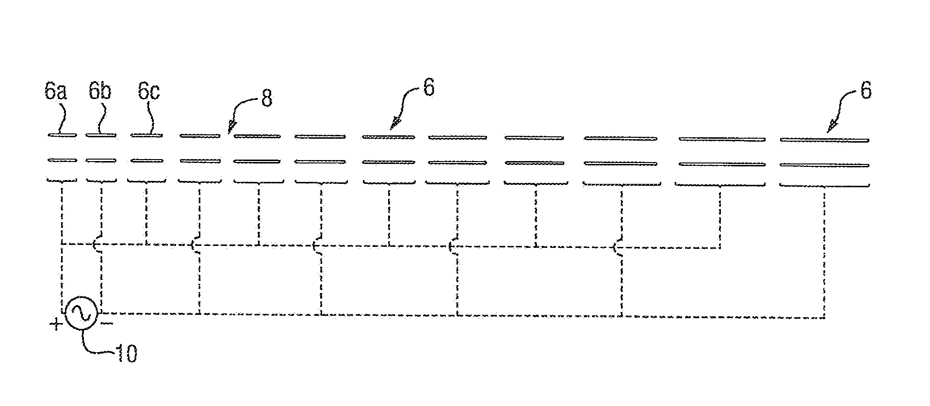
[0092]A time of flight (TOF) mass spectrometer operating in positive ion mode and having a two stage acceleration region and a two stage reflectron or ion mirror will now be described. However, it is also contemplated that the present invention may be applied to negative ion operation and to many other geometries of instrument.

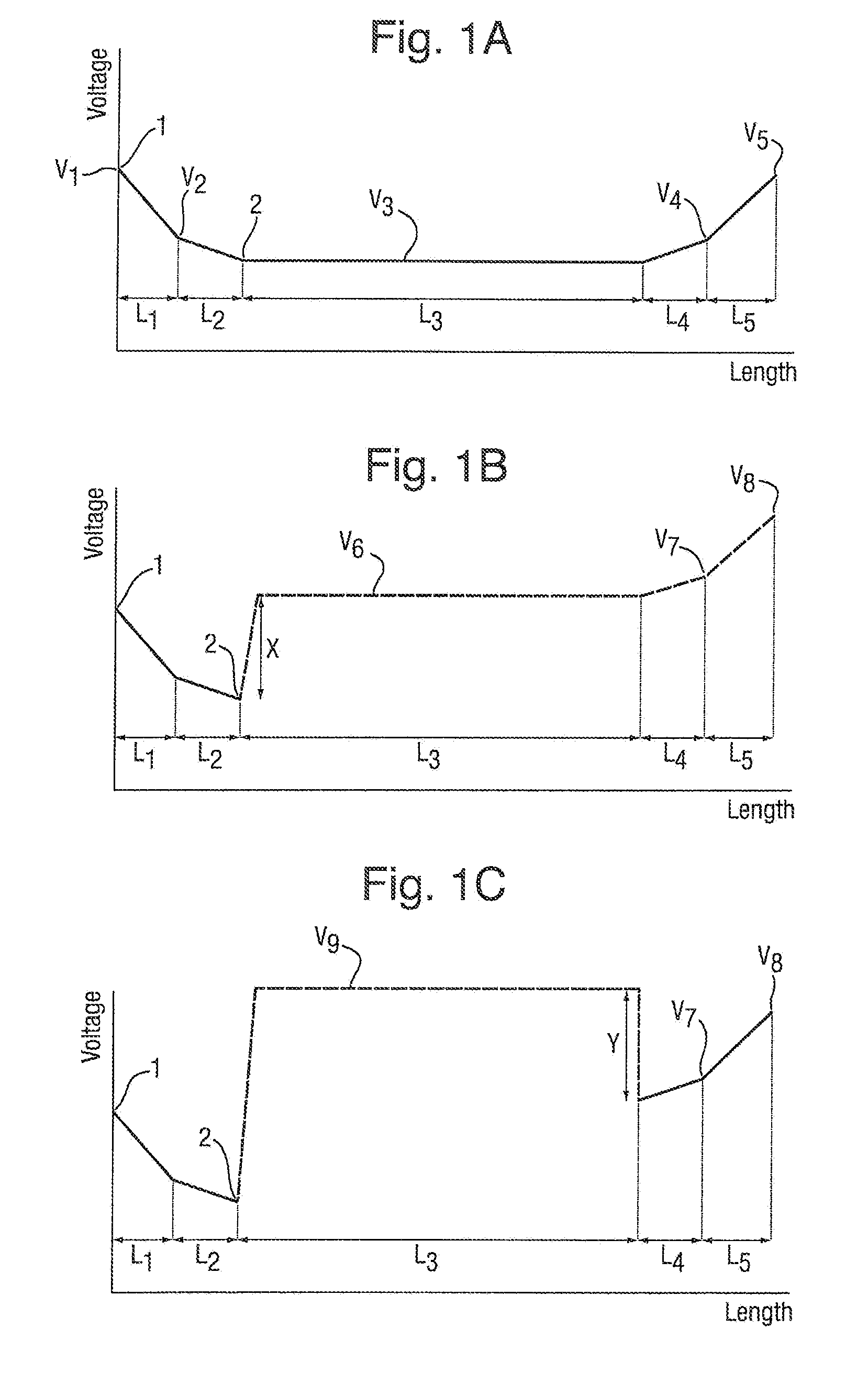
[0093]FIG. 1A shows a potential energy diagram of an orthogonal acceleration reflection TOF mass analyzer when being operated in a conventional manner. The diagram represents the relative potentials applied to the fixed electrodes within the TOE mass analyser. The potentials applied to the electrodes in FIG. 1A and the distance between these electrodes are as follows:

V1=2322.2 V

V2=0 V

V3=−627.8 V

V4=1641.2 V

V5=2322.2 V

L1=2.7 mm

L2=18 mm

L3=711 mm

L4=112 mm

L5=56.9 mm

[0094]This geometry provides third order spatial focusing for a 1 mm wide beam of ions, resulting in a theoretical mass resolution of approximately 30,000 FWHM.

[0095]The operation of the mass analyser wi...


PUM


Abstract

A method of mass spectrometry is disclosed comprising providing a flight region for ions to travel through and a detector or fragmentation device. A potential profile is maintained along the flight region such that ions travel towards the detector or fragmentation device. The potential at which a first length of the flight region is maintained is then changed from a first potential to a second potential whilst at least some ions are travelling within the first length of flight region. The changed potential provides a first potential difference at an exit of the length of flight region, through which the ions are accelerated as they leave the length of flight region. This increases the kinetic energy of the ions prior to them reaching the detector or fragmentation cell.

Description

CROSS-REFERENCE TO RELATED APPLICATION[0001]This application claims priority from and the benefit of United Kingdom patent application No. 1119059.2 filed on 4 Nov. 2011 and U.S. patent application No. 61 / 556,499 filed on 7 Nov. 2011. The entire contents of these applications are incorporated herein by reference.BACKGROUND TO THE INVENTION[0002]The present invention relates to a mass spectrometer and a method of mass spectrometry.[0003]Many time of flight (TOF) detector instruments employ electron multiplier detectors, such as microchannel plate detectors (MCPs) or discrete or continuous dynode detectors. A common feature of these detectors is that primary ions strike the detector, releasing secondary electrons which are guided to further electron multiplication stages. The conversion efficiency or electron yield from an ion strike to the production of secondary electrons defines the efficiency of the detector. Researchers have previously shown that the yield (λ) with which an ion g...

Claims


Application Information

Patent Timeline
IPC IPC(8): H01J49/40
CPCH01J49/06H01J49/40H01J49/403H01J49/0031H01J49/062
Inventor BROWN, JEFFERY MARKGREEN, MARTIN RAYMONDLANGRIDGE, DAVID J.
Owner MICROMASS UK LTD
Why Eureka
Try Eureka