Method of Providing Impact in Vacuum

a vacuum and impact technology, applied in the direction of electrical equipment, nuclear reactors, nuclear energy generation, etc., can solve the problems of evaporation of atoms from the surface, charge that can be placed on a macroscopic body, and 10 mg of a bullet mass to that speed, so as to achieve good vacuum, capture efficiency, and easy to be made sufficiently cold

Inactive Publication Date: 2014-08-21
JACK COLIN
View PDF4 Cites 6 Cited by
  • Summary
  • Abstract
  • Description
  • Claims
  • Application Information

AI Technical Summary

Benefits of technology

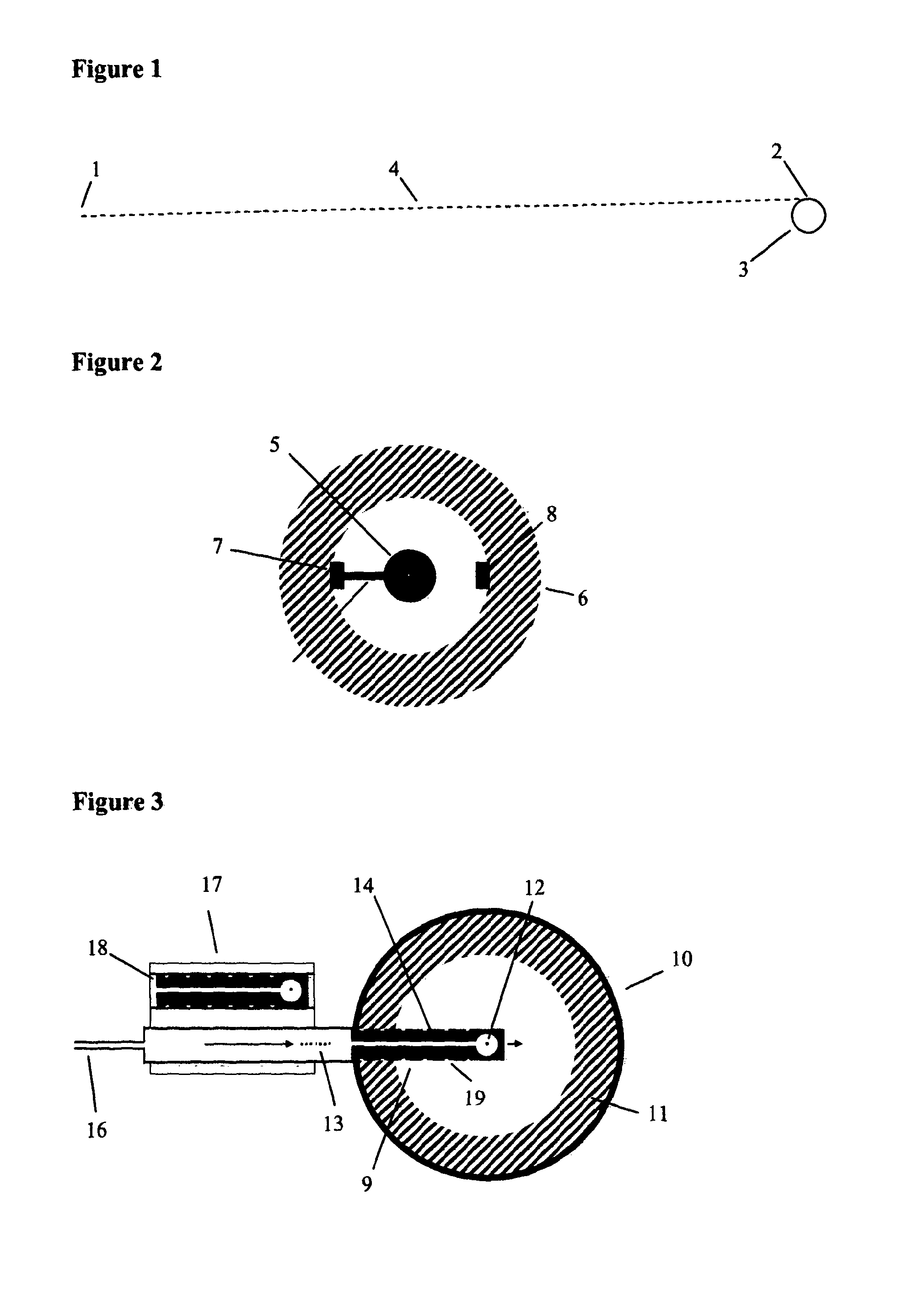
[0015]It is important to preserve a good vacuum behind the projectile. As the projectile proceeds into the chamber (10) any tendency of gas or plasma from within to escape via any gap between the sides of projectile and its enclosing tube to contaminate the vacuum behind the projectile is reduced or eliminated by the outer walls of the projectile being indented with one or more circumferential cavities (19) which act as traps for such escaping material. The projectile can easily be made sufficiently cold that the cavities (19) additionally act as cold traps for such escaping material.
[0016]As 100% capture efficiency is impossible, there can never be quite enough neutrons produced from DT reactions to replenish the tritium. To close the cycle, some DD reactions are therefore desirable, which produce both tritium directly and extra neutrons. This can be arranged by raising the impact speed, hence effective collision temperature, and / or as shown in FIG. 4 by packing material (20) richer in deuterium round the central DT target (21), optionally enclosed in a shell of denser material (22) to increase the confinement time: the outer shell has a hole (23) to permit entry of the particles.
[0017]While the above design is described as for space conditions, it is of course possible to implement it on Earth provided that a vacuum tube is provided through which the pellets pass as they travel from accelerator to target. It is possible to provide a perfectly straight line up to several hundred kilometres long on Earth by choice of suitable terrain, tunnelling, stringing a pipe between a coastline and an island with a deep-water trench in between, etc. It is also possible to deflect the course of the particles with electric or magnetic fields, so the vacuum tube can be bent to match local topography and the Earth's curvature. It is also possible to shorten the distance between the accelerator and the target to a more convenient value at the cost of increasing the power of the accelerator.

Problems solved by technology

However, firing a bullet massing ˜10 mg to that speed is extremely demanding.
Unfortunately the charge that can be placed on a macroscopic body is limited by self-repulsion, tending to cause both burst-apart and field effect evaporation of atoms from the surface.
The acceleration and vibration a macroscopic body can withstand is also a limiting factor.
Unfortunately multiple problems exist with this strategy, including the very high accelerator power that would be needed.

Method used


Image

  • Method of Providing Impact in Vacuum
  • Method of Providing Impact in Vacuum
  • Method of Providing Impact in Vacuum

Examples


Embodiment Construction

[0027]It might be thought that the ‘virtual bullet’ formed by the coalescing particles will be less dense than a normal solid of the same material, e.g. if the particles are perfect uniform spheres then at least by the ratio of the spherical packing fraction ˜0.74, and less than that if allowance is made for inevitable inaccuracies in their shape, position and size. However as the back layers of the bullet are travelling faster than the forward layers, the bullet will compress to many times the normal density of the raw material as (or just before or after) it strikes the target.

[0028]In each of FIGS. 5-9, parts (a), (b), (c) and (d) show particle positions (black circles) at consecutive timesteps en route to striking the target (hatched). For clarity the drawings are necessarily not to scale, with particle size vastly exaggerated, and particle number vastly reduced, compared to a likely implementation. FIG. 5 shows a basic configuration: particles come together to form a precompres...


PUM


Abstract

In space, a linear accelerator firing charged pellets can be situated at a large distance from a target at which the pellets are aimed. The accelerator can fire a graduated-speed train of pellets over a period of seconds or longer which arrive at the target simultaneously, and impart a large pulse of energy. An accelerator of modest power can thus provide a pulse in the megajoule range, sufficient to ignite fusion. It is necessary to provide course corrections to the pellets, to bring them together with very high precision as they approach the target. An ideal siting is to place the accelerator at the Earth-Moon L1 or L2 Lagrange point, and the fusion target at a point on the surface of the Moon where the pellets will strike at grazing incidence, i.e. on a great circle intersecting the lunar poles. Length of the particle trajectory is over 60000 km

Description

BACKGROUND OF THE INVENTION[0001]The possibility of igniting energy-generating fusion by impact, essentially by firing a bullet into a target at extreme speed 1000 km / sec, was studied in the 1960s and 1970s. However, firing a bullet massing ˜10 mg to that speed is extremely demanding. The most plausible method, then and now, is accelerating a charged bullet in a modified particle accelerator. Unfortunately the charge that can be placed on a macroscopic body is limited by self-repulsion, tending to cause both burst-apart and field effect evaporation of atoms from the surface. The acceleration and vibration a macroscopic body can withstand is also a limiting factor. Even the most optimistic estimates, using an ideal diamond as a ‘bullet’, put the necessary accelerator length at >100 km. An alternative is to use a cluster of microparticles (herein also referred to as particles or pellets) or heavy ions in place of a single bullet, which would reduce the accelerator length. Unfortuna...

Claims


Application Information

Patent Timeline
Patent Type & Authority Applications(United States)
IPC IPC(8): G21B1/15
CPCG21B1/15G21B1/19G21B3/006Y02E30/10
Inventor JACK, COLIN
Owner JACK COLIN
Why Eureka
Try Eureka