Low power laser CRT and projection system based on parallel flow electron gun

a projection system and laser technology, applied in the field of electromechanical technology, can solve the problems of shortening the average life of the chip, affecting the efficiency of the chip, so as to improve the heat dissipation effect, eliminate laser speckles, and reduce the cost

Inactive Publication Date: 2014-08-21
SHANGHAI FOREALIGHT SCI & TECH
View PDF6 Cites 1 Cited by
  • Summary
  • Abstract
  • Description
  • Claims
  • Application Information

AI Technical Summary

Benefits of technology

The present invention is a new laser light source that can produce high-speed laser beams. It uses a parallel flow electron gun to emit electron beams that have higher brightness and better decorrelation. This technology eliminates laser speckle and makes the laser more controllable. The laser panel has even current density distribution, which averages power consumption and reduces energy conversion to heat, leading to energy efficiency.

Problems solved by technology

The traditional CRT technology is being widely applied to TV and computer screen and also being applied to projection optical mechanical structures, but the efficiency is not very high and the brightness is limited.
The cross electron gun has many drawbacks in terms of light emitting mechanism, such as large proportion of energy is converted to heat, and the power consumption in the lightening area is not even, which will shorten the average life span of the chip.

Method used


Image

  • Low power laser CRT and projection system based on parallel flow electron gun
  • Low power laser CRT and projection system based on parallel flow electron gun
  • Low power laser CRT and projection system based on parallel flow electron gun

Examples


embodiment i

[0094]Referring to FIG. 5, three laser CRT1s provide red, green and blue laser light source respectively. Each laser CRT1 includes an electron beam current control system 14 to control the control electrode 133, and couples and shapes the laser light source produced by the laser CRT1 via a suitable X prism and projects it to the screen 6 via an optical projection system 5 to form a full color image. In order to achieve the color balance of the ideal projection image, the control electrode 133 of each laser CRT1 can solely be controlled via the electron beam current control system 14. The adjustment can be done manually. For example, let user solely control each laser CRT1. Or the electron beam current control system 14 can automatically adjusts the expected color balance via automatic feedback of a sensor.

embodiment ii

[0095]Referring to FIG. 6, three laser CRT1s provide red, green and blue laser light source respectively. Three laser CRT1s module the laser light via the optical modulator 7, couples and shapes the laser light via a suitable X prism, and projects it to the screen 6 via an optical projection system 5 to form a full color image. In order to achieve the color balance of the ideal projection image, each laser CRT1 can solely be adjusted via the electron beam current control system 14. The adjustment can be done manually. For example, let user solely control each laser CRT1. Or the electron beam current control system 14 can automatically adjusts the expected color balance via automatic feedback of a sensor.

embodiment iii

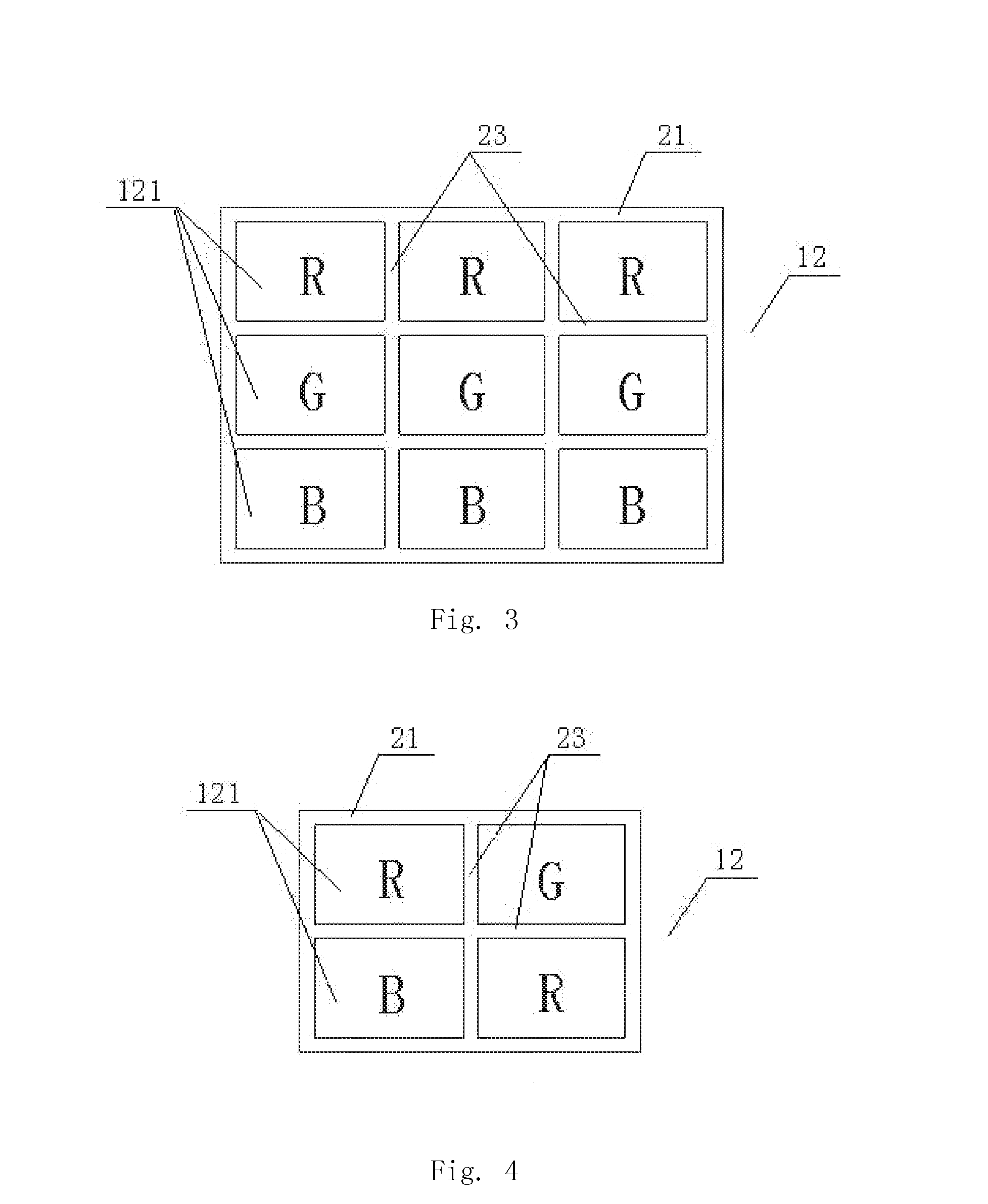
[0096]Referring to FIG. 7, the projection system only adopts one laser CRT1 that can produce three parallel beams of laser light source, wherein the three beams of laser light source are three primary colors respectively. Three beams of laser light source forms one beam of three-color synthesized light. This structure effectively saves the number of laser CRT, and reduces the space and cost of the projection system. When the laser CRT1 as shown in FIG. 7 is adopted, referring to FIG. 3, the laser panel 12 includes three rows of laser cavities 121, wherein the first row of laser cavity 121 uses red laser cavity of the three primary colors, marked with R; the second row of laser cavity 121 uses green laser cavity of the three primary colors, marked with G; the third row of laser cavity 121 uses blue laser cavity of the three primary colors, marked with B. The panel manifold 23 is provided between the neighboring two rows of laser cavities 121; the peripheral manifold pipe 21 is provid...


PUM


Abstract

The present invention relates to electronic technology field, and more particularly to CRT and projection system. A low power laser CRT based on parallel flow electron gun comprises a vacuum tube, a laser panel provided at one end of the vacuum tube and an electron gun provided at the opposing end. The electron gun adopts a parallel flow electron gun, wherein the parallel flow electron gun comprises a negative electrode, a G1 electrode and a control electrode, wherein the control electrode is connected to an electron beam current control system. The electron gun of the present invention adopts parallel flow electron gun to emit electron beam, so that the laser panel has even current density distribution so as to average the power consumption of laser panel to reduce the energy that is converted to heat.

Description

BACKGROUND OF THE PRESENT INVENTION[0001]1. Field of Invention[0002]The present invention relates to electronic technology field, and more particularly to CRT and projection system.[0003]2. Description of Related Arts[0004]With the emerging of the miniaturized and portable electronic equipment, the existing projection equipments usually adopt handheld and low power consumption projection equipment. The light source best suitable for this type of projection equipment is laser light source or light emitting diode. The laser light source is widely recognized as high efficient light source with low power consumption and high brightness.[0005]The projection system converts light emitted from light source to picture image by utilizing optical modulator. At present, this type of optical modulator usually uses projective / reflective liquid crystal display (LCD), liquid crystal on silicon (LCoS), and digital micro-mirror device (DMD) in Digital Light Procession (DLP) technology. Light source ...

Claims


Application Information

Patent Timeline
IPC IPC(8): H01J29/48G03B21/20
CPCG03B21/2033H01J29/481H01J29/48H01J31/10
Inventor XIA, ZHONGPINGZHAO, JIANYAN, YUANZHANG, XUEYUANZHONG, WEIJIE
Owner SHANGHAI FOREALIGHT SCI & TECH
Why Eureka
Try Eureka