
Step down switching regulator

a switching regulator and step-down technology, applied in the direction of dc-dc conversion, power conversion systems, electrical equipment, etc., to achieve the effect of improving circuit reliability and preventing the current from continuing to ris

Active Publication Date: 2014-08-07
ROHM CO LTD
View PDF0 Cites 18 Cited by
  • Summary
  • Abstract
  • Description
  • Claims
  • Application Information

AI Technical Summary

Benefits of technology

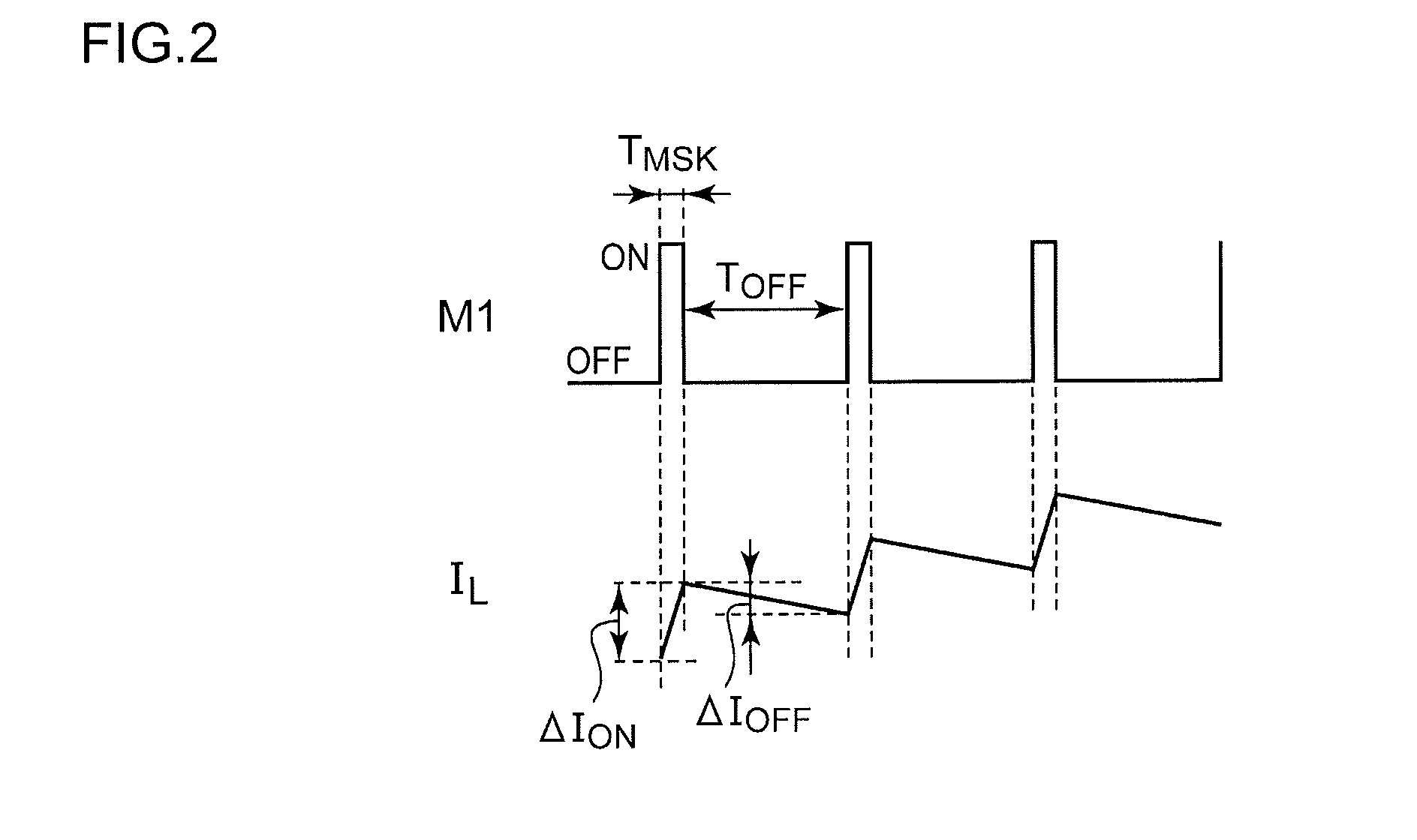
The present invention provides a solution for improving the reliability of a switching regulator, even when the output voltage is low. It does this by detecting and preventing an overcurrent state that can occur due to a ground fault at the output terminal of the switching transistor. This prevents the switching transistor from switching to the first level, which would allow the coil current to continually rise and cause further damage to the circuit. As a result, the invention improves circuit reliability.

Problems solved by technology

As a result, immediately after the switching transistor M1 is turned on, and before the coil current reaches a sufficiently increased value, the switching transistor M1 is turned off, which is a problem.

Method used


Image

  • Step down switching regulator
  • Step down switching regulator
  • Step down switching regulator

Examples


Embodiment Construction

[0040]The invention will now be described based on preferred embodiments which do not intend to limit the scope of the present invention but exemplify the invention. All of the features and the combinations thereof described in the embodiment are not necessarily essential to the invention.

[0041]In the present specification, the state represented by the phrase “the member A is connected to the member B” includes a state in which the member A is indirectly connected to the member B via another member that does not substantially affect the electric connection therebetween, or that does not damage the functions or effects of the connection therebetween, in addition to a state in which the member A is physically and directly connected to the member B.

[0042]Similarly, the state represented by the phrase “the member C is provided between the member A and the member B” includes a state in which the member A is indirectly connected to the member C, or the member B is indirectly connected to ...


PUM


Abstract

A current limiting comparator generates a current limiting signal SLIM which is asserted when a detection voltage Vs at a detection terminal CS is higher than a predetermined threshold voltage VTH. A mask signal generating unit generates a mask signal SMSK which is asserted after a predetermined delay time TMSK elapses after a switching transistor is turned on. A pulse signal generating unit has: a function (a) in which, when the set signal SSET is asserted in a period in which the current limiting signal SLIM is negated, a pulse signal SPWM is switched to a first level; and a function (b) in which, when the reset signal SRST is asserted, or when the current limiting signal SLIM is asserted in a period in which the mask signal SMSK is negated, the pulse signal SPWM is switched to a second level.

Description

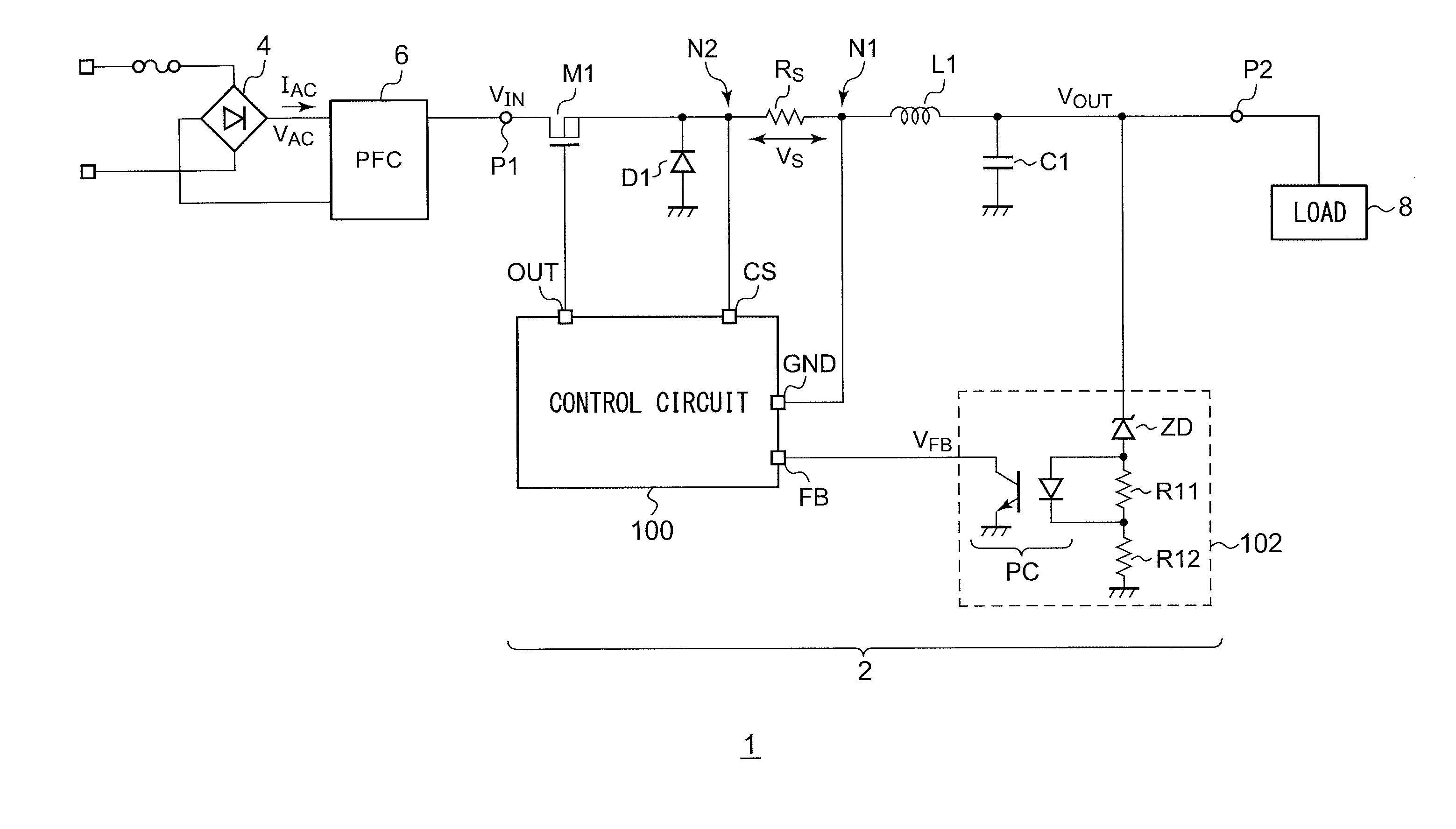
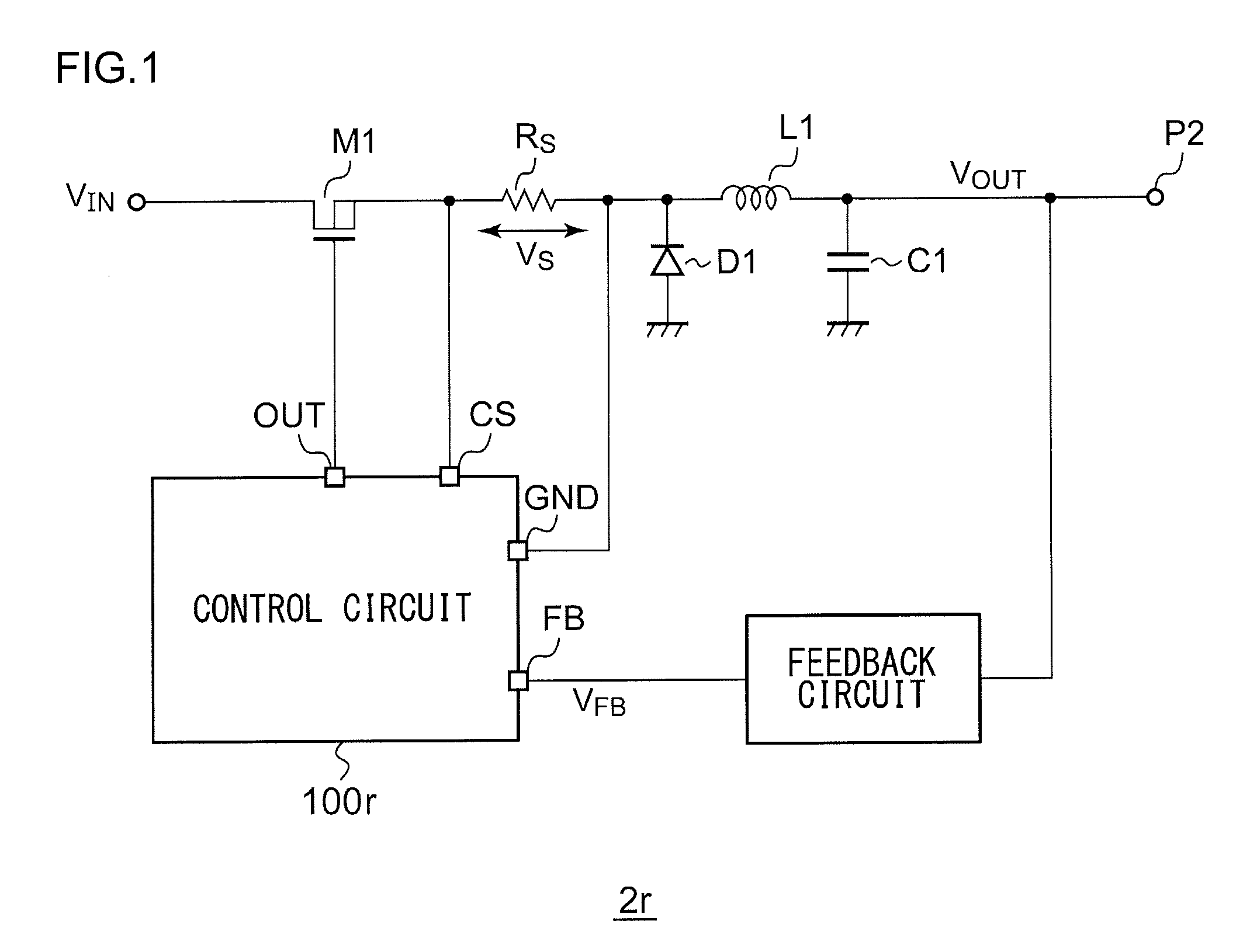
BACKGROUND OF THE INVENTION[0001]1. Field of the Invention[0002]The present invention relates to a non-insulated step-down switching regulator (DC / DC converter).[0003]2. Description of the Related Art[0004]Various kinds of consumer electronics devices such as TVs, refrigerators, etc., or otherwise electronic devices such as laptop computers, cellular phone terminals, and PDAs (Personal Digital Assistants), each mount a switching regulator which steps down a DC voltage to a voltage level that corresponds to a load.[0005]FIG. 1 is a circuit diagram showing a configuration of a non-insulated step-down switching regulator investigated by the present inventors. A switching regulator 2r steps down a DC input voltage VIN input to its input terminal P1, and outputs the voltage thus stepped down to its output terminal P2.[0006]The switching regulator 2r includes a switching transistor M1 configured as an N-channel MOSFET, a rectifier diode D1, an inductor L1, an output capacitor C1, a curren...

Claims


Application Information

Patent Timeline
Patent Type & Authority Applications(United States)
IPC IPC(8): H02M7/06
CPCH02M7/06H02M3/156H02M1/0009H02M1/0003
Inventor HAYASHI, HIROSHISATO, YOSHINORINATE, SATORU
Owner ROHM CO LTD
Learn More