
Coaxial-impedance synthesizer

a technology of coaxial impedance and synthesizer, which is applied in the direction of impedence networks, waveguide devices, electrical devices, etc., can solve the problems of increasing the time required to synthesize, load leakage, and adversely affecting the speed of deck movement, so as to achieve a high reflection coefficient

Active Publication Date: 2014-07-10
CURUTCHET ARNAUD
View PDF2 Cites 3 Cited by
  • Summary
  • Abstract
  • Description
  • Claims
  • Application Information

AI Technical Summary

Benefits of technology

The patent describes a probe that can be easily mounted around a conductor and has good electrical contact, resulting in the best performance. The probe can be positioned precisely, resulting in repeatable impedance measurements. There is no friction or wear between the probe and the conductor, and the microwave performance is higher than other systems. The invention also allows for impedance synthesizers to operate over a wide range of frequencies.

Problems solved by technology

Moreover, such plungers 4 may cause load leaks.
The velocity of movement of the decks is adversely affected, which has the effect of increasing the time required to synthesize impedances that require a displacement of the decks.
Due to this design, vibration may occur at the diver(s), which can alter the performance of the tuner.
The vibrations generated by the tuner can also cause degradation of the contacts of the components measured on-wafer.
Furthermore, this mode of conception leads to bulky and relatively heavy tuners, which penalizes their use for measurements on probing tip station for on-wafer characterization.
Due to their bulkiness, it is impossible to place these tuners very close to the components measured, which inevitably increases the insertion loss and therefore ‘dead zones’ on the Smith chart.
However, these systems are particularly rigid, which increases the problems of vibration at the tip ends and of degradation of the components contacts.
In extreme cases, this can cause the destruction of the measured component, or of the microwave tips.
Finally, the most stringent problem of the plunger-type tuners is their reliability.
The tuner has many limitations, and the electromagnetic performance is not optimal.
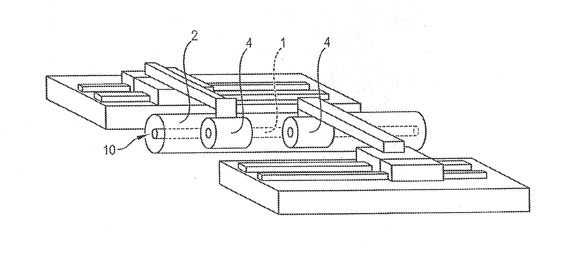
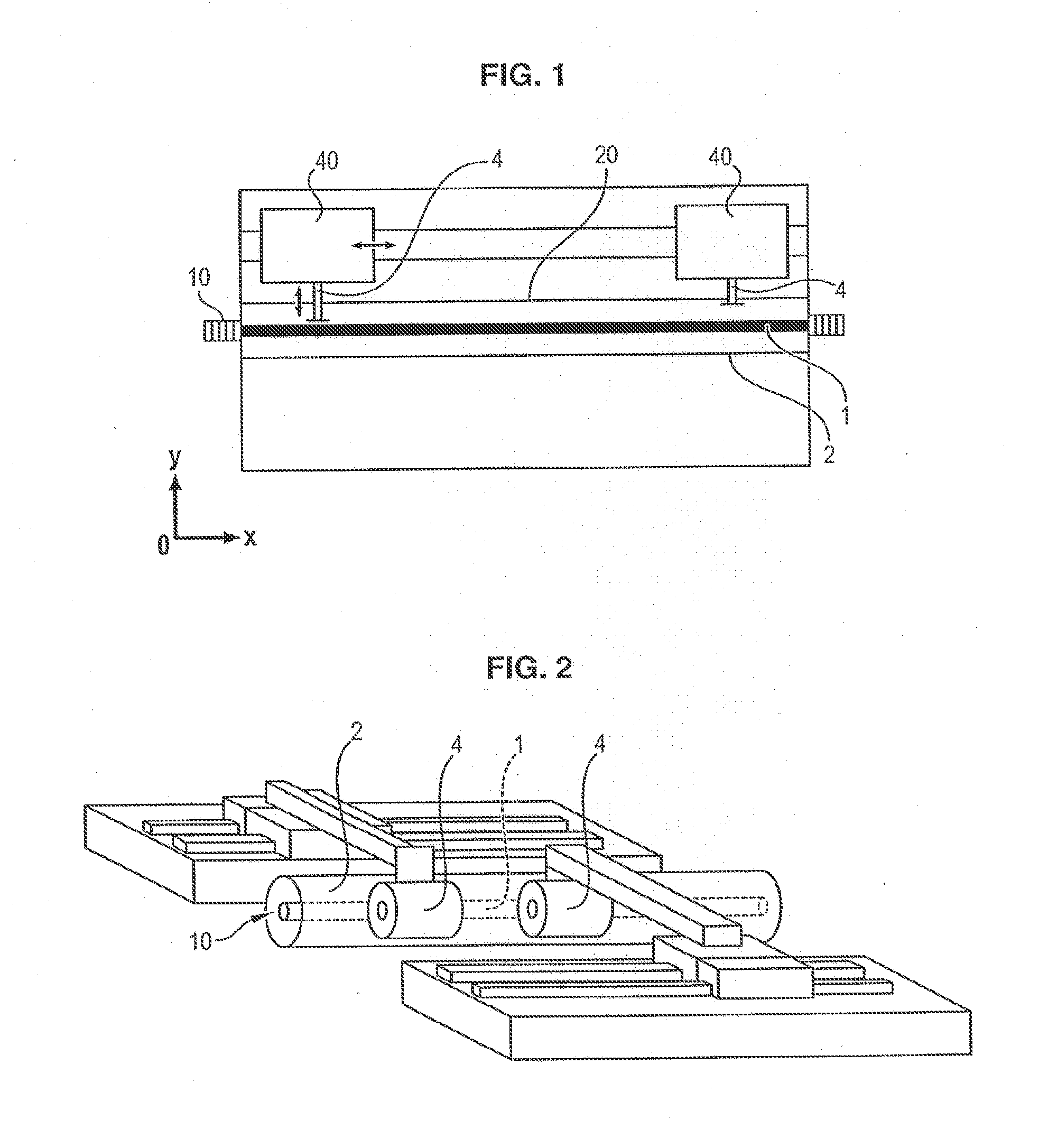
Apart from the fact that the displacement of the probes 4 generates unavoidable wearing by friction, this play makes the electrical contact between the outside of the proves 4 and the inside of the tube 2 forming the outer conductor of the coaxial conductor poor and inhomogeneous.
This problem inevitably leads to problems of repeatability, making the use of the tuner impossible for characterizating an electronic component.
Moreover, if the probes 4 take slightly askew positions, this can cause a destruction of the mechanism if one of the probes 4 gets caught on any asperity present inside the outer conductor 2.
Another major flaw of the tuner according to FIG. 2 is the impossibility to obtain an impedance of 50Ω in use, since it would require to remove the probes 4.
In addition, changing the probes 4 is not easy, since it requires that they exit at one of the ends of the coaxial conductor, requiring a systematic disassembly of the microwave connectors.
However, the performance of the latter is not guaranteed beyond a certain number of assembling / disassembling operations.
The use of any lubrication means remains excluded due to the electromagnetic problems that it would generate.

Method used


Image

  • Coaxial-impedance synthesizer
  • Coaxial-impedance synthesizer
  • Coaxial-impedance synthesizer

Examples


Embodiment Construction

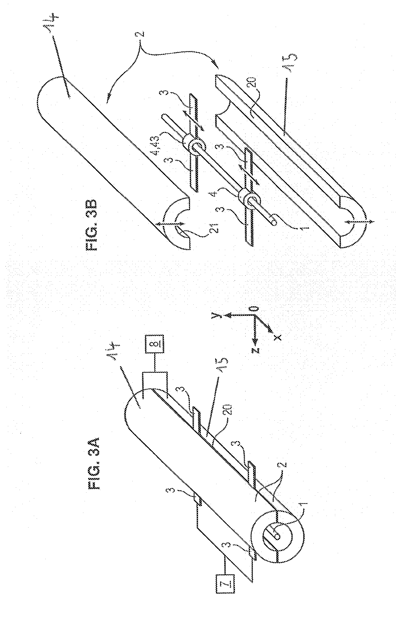
[0077]FIGS. 3A and 3B diagrammatically show a possible embodiment of an impedance synthesizer according to the invention.

[0078]The impedance synthesizer mainly includes a central longitudinal 1 conductor extending along a longitudinal axis Ox and a conductive outer tube 2 coaxial with the conductor 1 (referred thereafter as outer tube).

[0079]The outer tube 2 comprises two separable half-tubes 14, 15.

[0080]In FIGS. 3-5, the tube is cylindrical. However, this is not mandatory and the tube may be square or rectangular. The same applies to the two half-tubes. In addition, the two half-tubes are not necessarily identical. Whatever the tube section is, it is hollow and longer than wide.

[0081]The half tubes define at least two positions: a position of away from each other, illustrated in a non-limiting manner in FIG. 3B, and a position of mutual closeness, illustrated in a non-limiting manner in FIG. 3A.

[0082]The two half-tubes are not necessarily completely separable pieces, and can may b...


PUM


Abstract

The invention relates to a coaxial-impedance synthesizer, comprising: a longitudinal central (0x) conductor (1); an outer conductive tube (2) arranged coaxially to the conductor (1); and at least one probe (4) mounted so as to longitudinally translate around the conductor (1), the coaxial-impedance synthesizer being characterized in that the outer tube (2) includes two separable half-tubes, such that the probe (4) is permitted to move longitudinally, relative to the central conductor (1), to a desired position when the two half-tubes are spaced apart from each other, and when the two half-tubes are near each other, the outer periphery of the probe (4) and the inner wall of the outer tube are in contact with each other.

Description

GENERAL TECHNICAL FIELD[0001]The present invention relates to the field of microwave electronics, for example for measurement instruments.PRESENTATION OF THE PRIOR ART[0002]As shown in FIG. 1, impedance adapters (also known as ‘tuners’ by those skilled in the art) are known, which comprise a coaxial conductor, the outer part 2 of which is cut by a slit 20 in the direction of its length, indicated by axis Ox. This slit 20 allows the passage of one or more plunger-type probes 4 that can be displaced independently from each other not only along the axis Ox, but also along the axis Oy orthogonal to Ox. By changing the distance separating each plunger 4 from a central conductor 1 of the coaxial conductor 1, the characteristic impedance of the corresponding line end 10 is changed. When the plunger(s) 4 is / are maximally remote from the central conductor 1, the tuner shows an impedance of 50Ω.[0003]There also exists mobile carriages 40 equipped in automatic versions with motors ensuring the...

Claims


Application Information

Patent Timeline
Patent Type & Authority Applications(United States)
IPC IPC(8): H03H7/38
CPCH01P5/04H03H7/38H03H7/40
Inventor CURUTCHET, ARNAUD
Owner CURUTCHET ARNAUD
Learn More