Piezoelectric pressure sensor

Active Publication Date: 2014-07-10
COMMISSARIAT A LENERGIE ATOMIQUE ET AUX ENERGIES ALTERNATIVES
View PDF3 Cites 22 Cited by
  • Summary
  • Abstract
  • Description
  • Claims
  • Application Information

AI Technical Summary

Benefits of technology

The invention provides a pressure sensor with a simple and inexpensive design that has high sensitivity. The piezoelectric layer in the sensor has dipoles aligned along the direction of the exerted pressure, which increases the number of collected charges and sensitivity. The alignment can be done once before use and is achieved by applying an electric field between selected electrodes. The electric field should be between 0.3 and 0.7 volts per micrometer and the temperature should be between 40 to 60°C for a time period between 20 minutes to 8 hours. This improves the charge mobility and allows for faster and more complete alignment.

Problems solved by technology

However, even though such pressure sensors are robust and reliable, they have a low sensitivity.
This type of variable-capacitance pressure sensor enables to measure the capacitance variation between a metallic diaphragm and a fixed metal plate, and is generally very stable and linear; however, such capacitances are sensitive to high temperatures and are more complex to install than most pressure sensors.
However, it is particularly difficult to measure small voltage variations, so that such piezoelectric pressure sensors are considered as having a low sensitivity, that is, as being unable to measure low pressures or low pressure variations.

Method used


Image

  • Piezoelectric pressure sensor
  • Piezoelectric pressure sensor
  • Piezoelectric pressure sensor

Examples


Embodiment Construction

[0039]For clarity, in the following description, the same elements have been designated with the same reference numerals in the different drawings. Further, the various cross-section views are not necessarily drawn to scale.

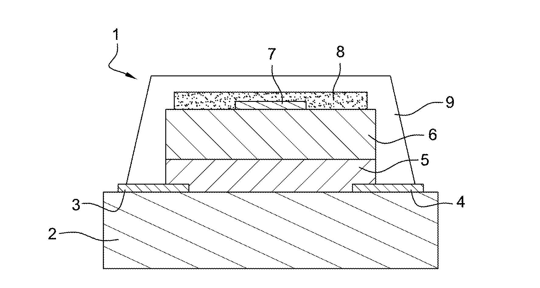
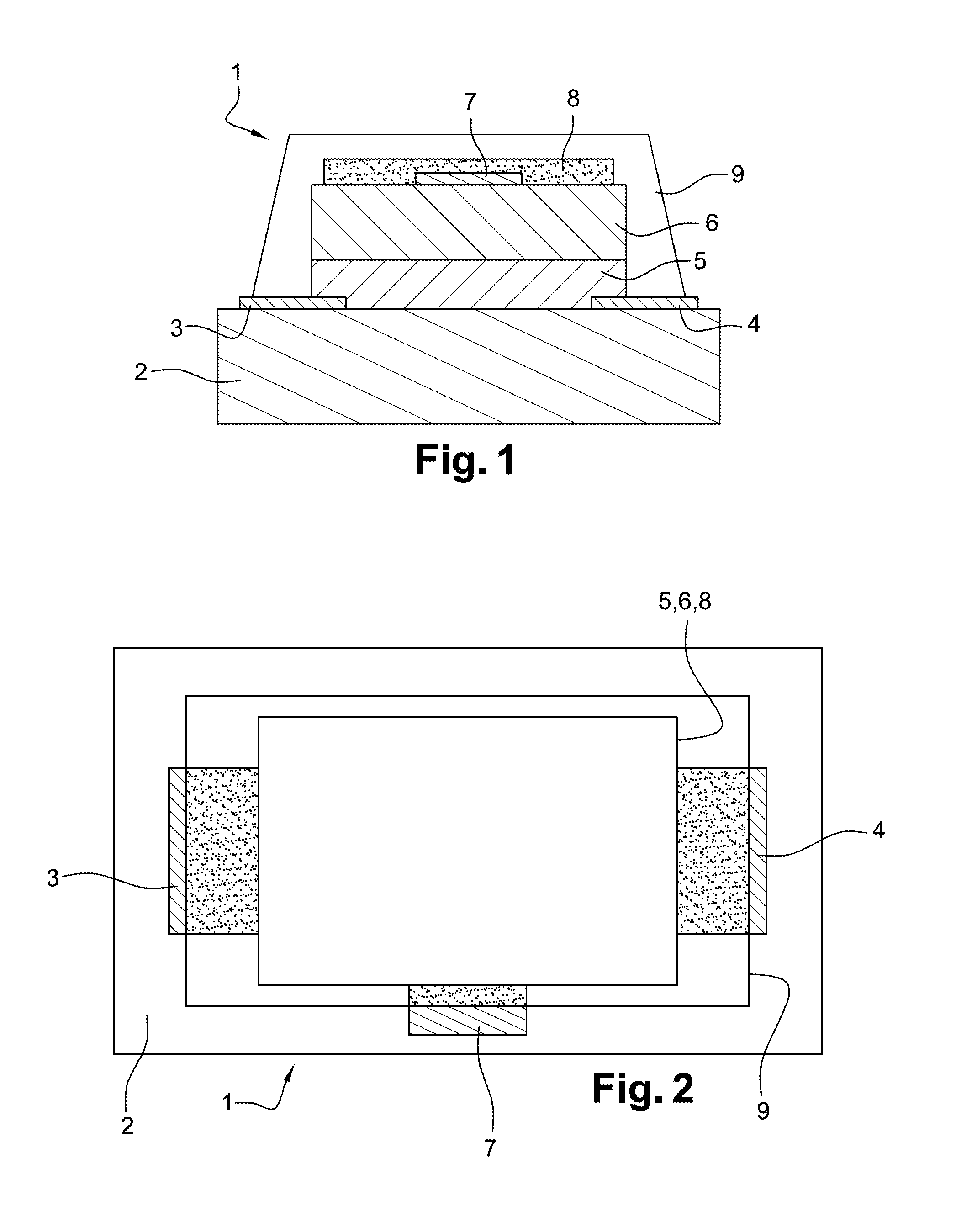
[0040]Referring to FIGS. 1 and 2, pressure sensor 1 according to the invention comprises a lower substrate 2, having two electrodes 3, 4 deposited thereon, respectively a source electrode 3 and a drain electrode 4.

[0041]Lower substrate 2 is made of a material selected from the following list: glass, doped or undoped silicon substrate, polymers such as polyethylene terephthalate (PET), polyethylene naphthalate (PEN), polyimide (PI), polycarbonate, acrylates, etc.

[0042]It should however be obvious that lower substrate 2 may be obtained in any other material well known by those skilled in the art.

[0043]Further, source and drain electrodes 3 and 4 are made of metal, such as aluminum, titanium, nickel, gold, chromium, etc . . . , or of metal particles, of metal oxides...


PUM


Abstract

A pressure sensor including a lower substrate having two electrodes partially covered with a semiconductor layer and a piezoelectric layer made of a piezoelectric material, and in contact with the semiconductor layer in such a way that semiconductor material is in contact with the piezoelectric material and with the two electrodes, deposited thereon. The electrodes are intended to be connected to a voltage source or to a device for measuring the intensity of a current generated by the displacement of the electric charges in the semiconductor layer between the electrodes, said electric charges being created when a pressure is exerted on the piezoelectric layer.REPLACEMENT SHEET

Description

TECHNICAL DOMAIN[0001]The present invention relates to a pressure sensor, and more specifically, to a pressure sensor comprising a piezoelectric material.BACKGROUND[0002]To measure a pressure, that is, a force applied to a surface, it is well known to use different types of pressure sensors.[0003]The most current pressure sensors are strain gauge sensors. Such sensors operate by implementing a piezoresistive effect, that is, the effect of a pressure on the characteristics of a resistor called strain gauge. The geometric variation of a strain gauge translates as a variation of its resistance. Such sensors comprise four strain gauges, such as a wire gauge, a foil strain gauge, or a semiconductor gauge, for example, assembled as a Wheatstone bridge on a deformable proof body. The variations of the gauge resistances then enable to determine the pressure exerted on the proof body.[0004]However, even though such pressure sensors are robust and reliable, they have a low sensitivity.[0005]P...

Claims


Application Information

Patent Timeline
IPC IPC(8): H01L41/193
CPCH01L41/193G01L9/008G01L9/06G01L9/08G01L1/16H10N30/302H10N30/857
Inventor BENWADIH, MOHAMMEDALIANE, ABDELKADER
Owner COMMISSARIAT A LENERGIE ATOMIQUE ET AUX ENERGIES ALTERNATIVES
Why Eureka
Try Eureka