Smart charging system for hybrid battery pack

a hybrid battery pack and charging system technology, applied in the field of computing systems, can solve the problems of deep discharge, irreversible reduction of battery capacity, and only moderate power density of lithium polymer batteries, and achieve the effect of large energy density and large power density

Inactive Publication Date: 2014-06-26
NVIDIA CORP
View PDF9 Cites 9 Cited by
  • Summary
  • Abstract
  • Description
  • Claims
  • Application Information

AI Technical Summary

Benefits of technology

[0008]Therefore, it would be advantageous to provide a battery system to a mobile computing device with both large energy density and large power density, so that the battery system can reliably supply transient currents to the device without its operating lifetime and capacity being eroded over time by the transient currents.

Problems solved by technology

However, Li polymer batteries usually have only moderate power density and cannot tolerate fast charge or discharge rates due to the nature of the chemical reactions in the cells.
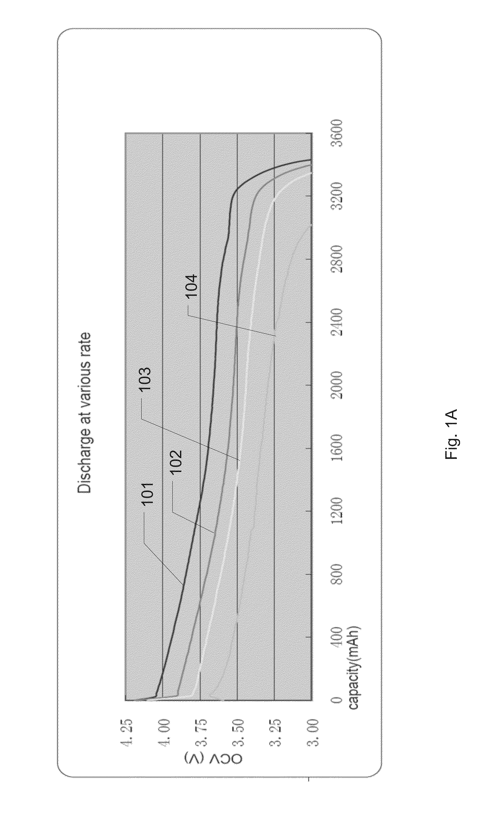
Typically, the maximum battery discharging rate is 1 C and a larger discharging rate may irreversibly reduce the battery capacity.
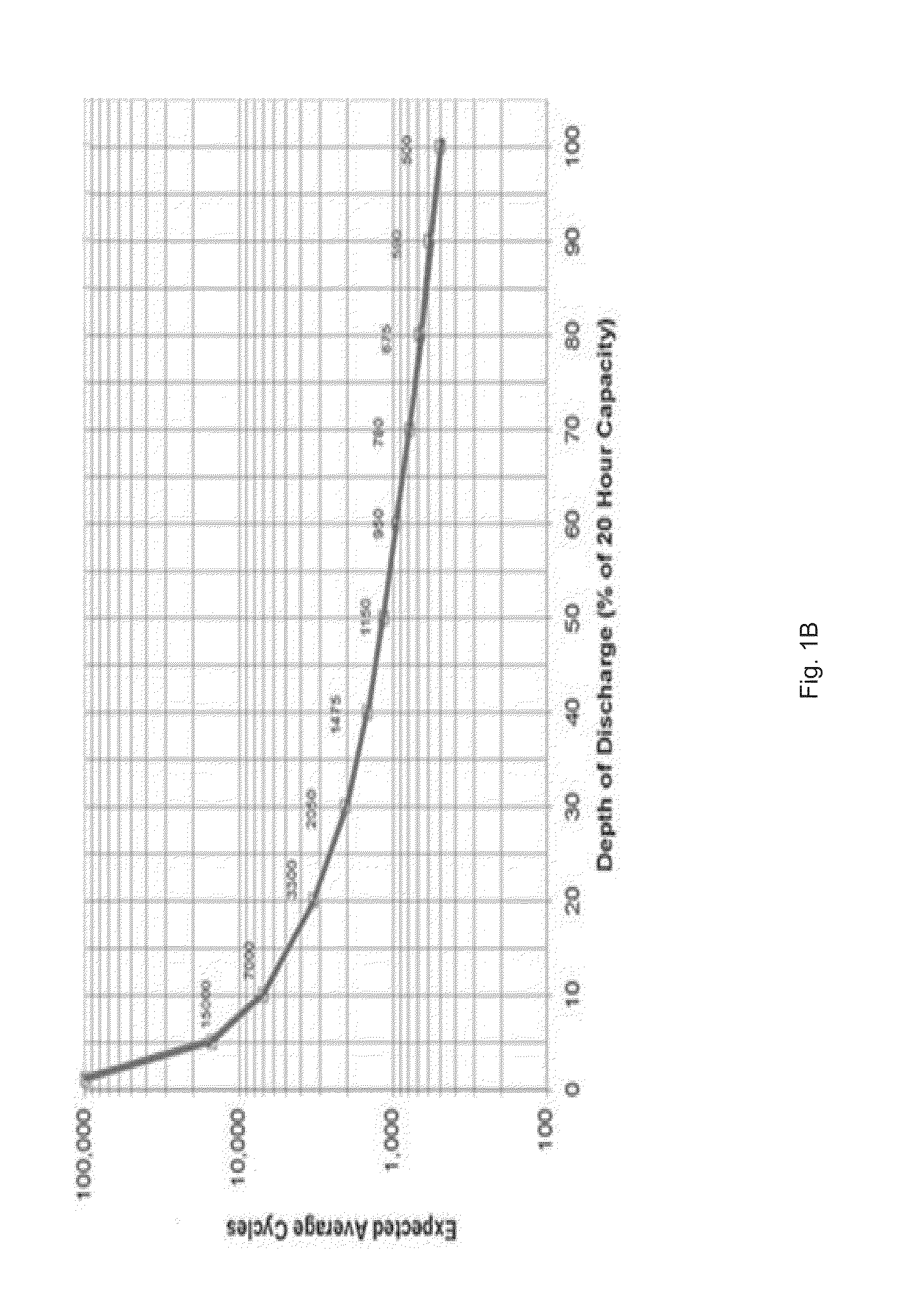
Transient currents are problematic to Li polymer batteries because they discharge the battery at high rates and likely cause deep discharge in a short time period.
As a consequence, the operating lifetime of Li polymer batteries tends to deteriorate.
In addition, Li polymer cells generally have relatively large internal impedance which renders slow responses to transient currents.
High transient currents that exceed the maximum battery discharging limitation may frequently occur during the operations of the devices, for instance, when a hardware component is activated from a low power state to a high power state in a very short time interval.
Therefore, a user typically experiences battery capacity declining over time and battery lifetime being shorter than claimed by the manufacturer.

Method used


Image

  • Smart charging system for hybrid battery pack
  • Smart charging system for hybrid battery pack
  • Smart charging system for hybrid battery pack

Examples


Embodiment Construction

[0020]Reference will now be made in detail to the preferred embodiments of the present invention, examples of which are illustrated in the accompanying drawings. While the invention will be described in conjunction with the preferred embodiments, it will be understood that they are not intended to limit the invention to these embodiments. On the contrary, the invention is intended to cover alternatives, modifications and equivalents, which may be included within the spirit and scope of the invention as defined by the appended claims. Furthermore, in the following detailed description of embodiments of the present invention, numerous specific details are set forth in order to provide a thorough understanding of the present invention. However, it will be recognized by one of ordinary skill in the art that the present invention may be practiced without these specific details. In other instances, well-known methods, procedures, components, and circuits have not been described in detail ...


PUM


Abstract

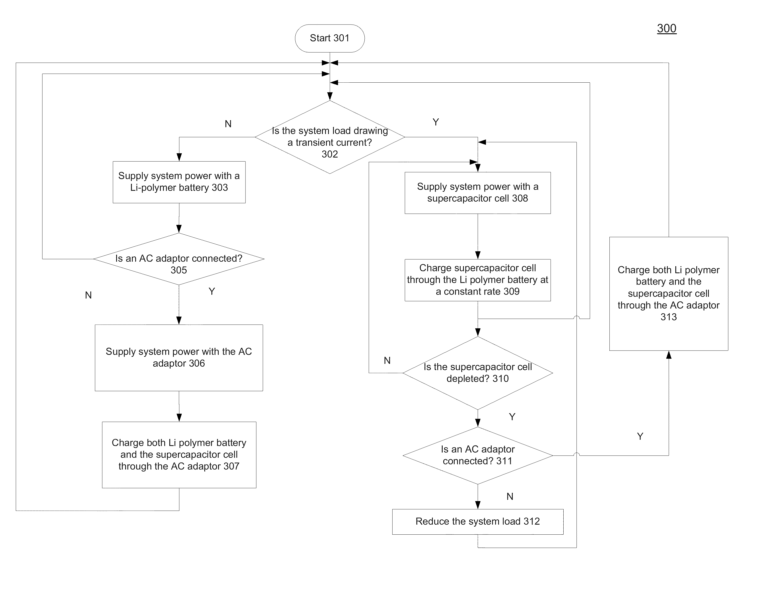
A hybrid battery pack and a power supply procedure for supplying power to a mobile computing system comprising a Li polymer battery coupled in parallel with a supercapacitor cell battery. The Li polymer battery supplies substantially all the continuous currents demanded by the system load. The supercapacitor cell battery supplies substantially all the transient current demanded by the system load. A charging control logic circuit is coupled to the power source and the system load, and operable to control the Li polymer battery to charge the supercapacitor cell battery at a constant rate while the supercapacitor cell battery supplies current to the system load. The control logic can also send instructions to have system load reduced if the supercapacitor cell battery is depleted before it can be charged with an external charger.

Description

TECHNICAL FIELD[0001]The present disclosure relates generally to the field of computing systems and more specifically to the field of power supplies for computing systems.BACKGROUND[0002]With the development of application programs, display qualities and storage capabilities of mobile devices, as well as the exponential growth of Internet information, the functions of mobile computing devices, including laptops, PDAs, media players, touchpads, smartphones, etc., have been increasingly expanded and refined. Accordingly, users have demanded longer continuous runtime of mobile devices. Thus, the operating lifetime of a battery has become one of the critical features of such products as it determines the utility of the mobile device in the normal situation where wall power is not easily accessible.[0003]Mobile devices are commonly fitted with rechargeable Li-ion polymer batteries, or Li polymer batteries, which convert chemical energy to electrical energy through redox reactions. Li pol...

Claims


Application Information

Patent Timeline
Patent Type & Authority Applications(United States)
IPC IPC(8): G06F1/26G06F1/32
CPCG06F1/263G06F1/3206
Inventor HUA, JEVONS
Owner NVIDIA CORP
Why Eureka
Try Eureka