
Laser apparatus and photoacoustic apparatus using laser apparatus

Inactive Publication Date: 2014-05-08
CANON KK
View PDF25 Cites 6 Cited by
  • Summary
  • Abstract
  • Description
  • Claims
  • Application Information

AI Technical Summary

Benefits of technology

The invention provides a technique for a tunable laser apparatus that allows for stable wavelength selection and laser oscillation. This solves a problem that previously existed and ensures the laser operates efficiently and effectively.

Problems solved by technology

Mechanical rotation of an optical component for the selection of wavelength involves the problem of a possible drop of output energy or wavelength displacement caused by a misalignment of rotation axis and a resultant misalignment of optical axis.
However, one problem with the acousto-optical element is large intracavity loss because of its diffraction efficiency being normally 70% to 80%, even with primary diffraction light.
Also, acousto-optical elements can hardly be applied to a high power laser apparatus because of their limited light resistance.

Method used


Image

  • Laser apparatus and photoacoustic apparatus using laser apparatus
  • Laser apparatus and photoacoustic apparatus using laser apparatus
  • Laser apparatus and photoacoustic apparatus using laser apparatus

Examples


embodiment 1

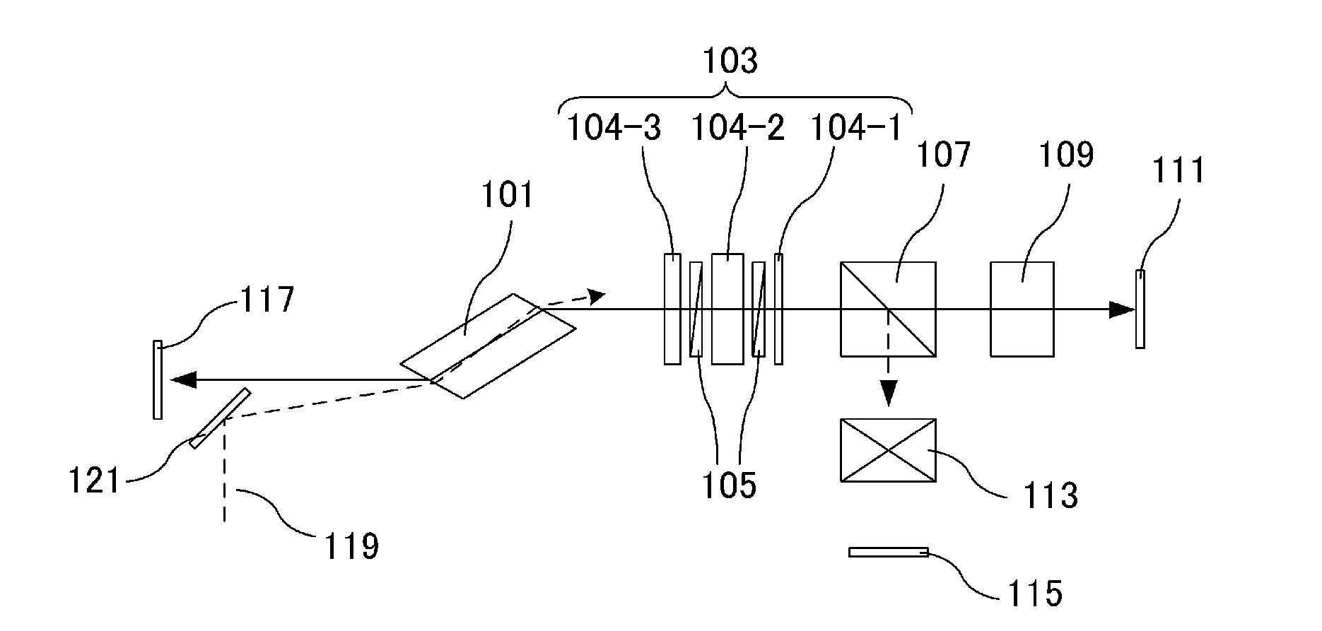
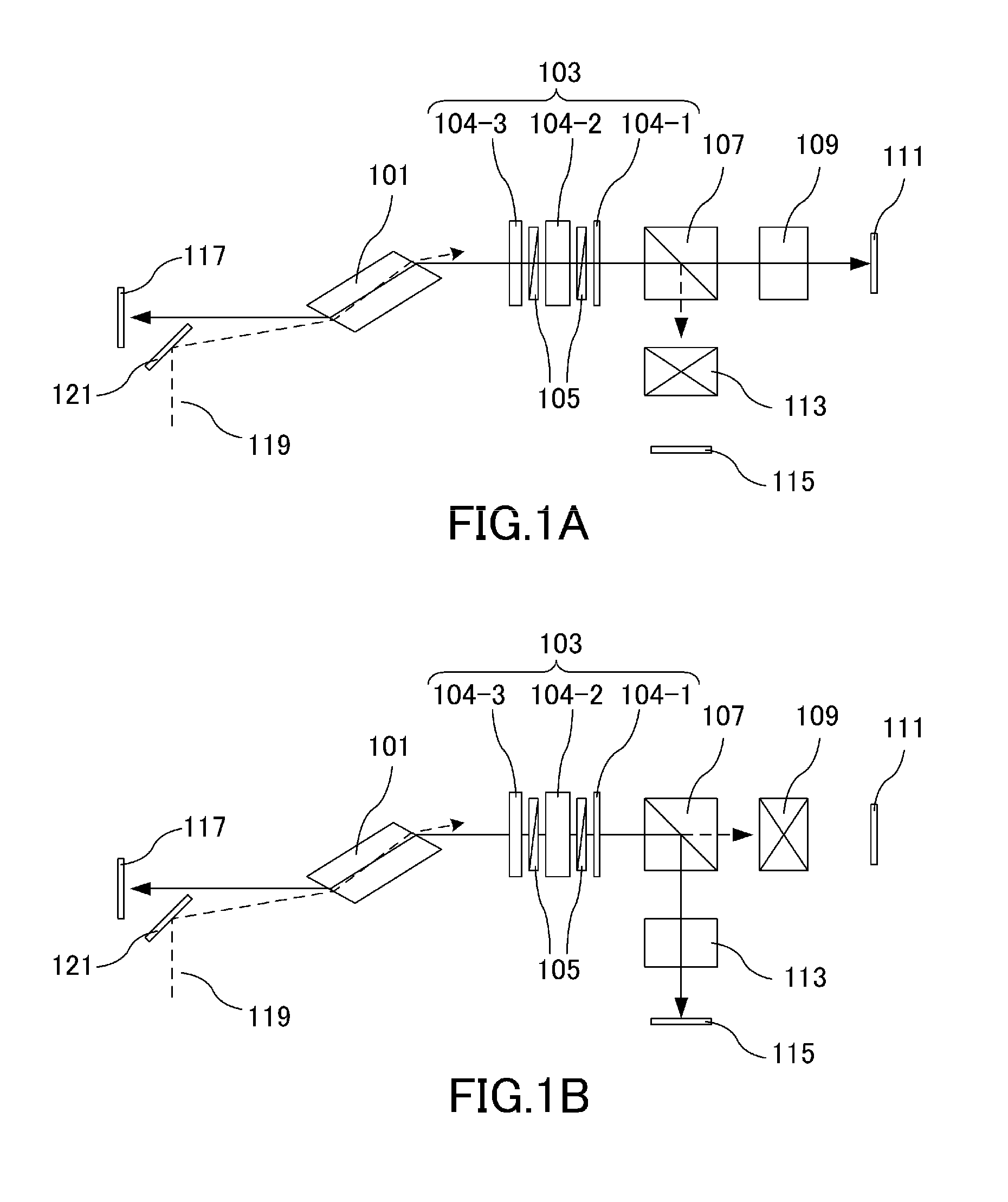
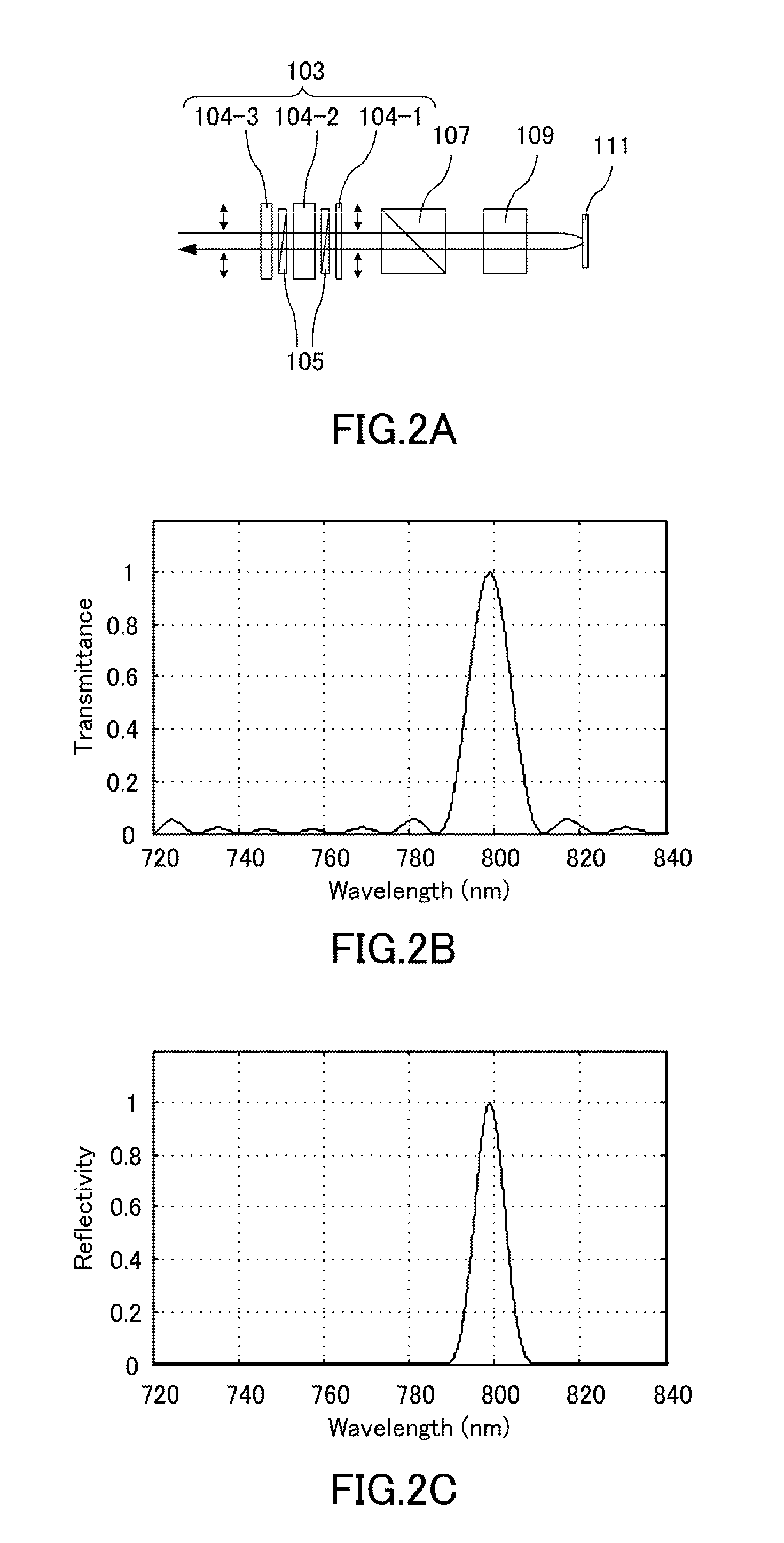
[0067]A laser apparatus according to a first embodiment will be described further with reference to FIG. 1A and FIG. 1B. Reference numeral 101 in the drawing denotes a laser medium made of titanium sapphire crystal that is cut to have an end face at the Brewster's angle relative to resonating light. Reference numeral 103 denotes a wavelength filter that is formed by three birefringent plates 104-1, 104-2, and 104-3, and two polarizing plates 105. Reference numeral 107 denotes a polarizing beam splitting element which is a polarizing beam splitter that transmits p-polarized light and reflects s-polarized light. Reference numeral 109 denotes first light shielding means which is an optical shutter provided to the first cavity. Reference numeral 111 denotes a first rear mirror having a reflectivity of 99%. Reference numeral 113 denotes second light shielding means which is an optical shutter provided to the second cavity. Reference numeral 115 denotes a second rear mirror having a refle...

embodiment 2

[0085]FIGS. 6A and 6B are schematic diagrams for explaining a second embodiment of the laser apparatus of the present invention. Elements that are common to the first embodiment are given the same reference numerals and will not be described again. The difference from the first embodiment is the configuration of the wavelength filter.

[0086]In FIG. 6A and FIG. 6B, reference numeral 201 denotes the wavelength filter that is formed by three birefringent plates 202-1, 202-2, and 202-3. The birefringent plate 202-1 is made of quartz crystal having the optical axis perpendicular to the thickness direction and a thickness of 0.7 mm (equal to one time the “predetermined thickness”). The birefringent plate 202-2 is made of quartz crystal having the optical axis perpendicular to the thickness direction and a thickness of 2.8 mm (equal to four times the “predetermined thickness”). The birefringent plate 202-3 is made of quartz crystal having the optical axis perpendicular to the thickness dire...

embodiment 3

[0104]FIGS. 11A and 11B are schematic diagrams for explaining a third embodiment of the laser apparatus of the present invention. Elements that are common to the first embodiment are given the same reference numerals and will not be described again. The difference from the first embodiment is the configurations of the wavelength filter and the laser medium.

[0105]In FIG. 11A and FIG. 11B, reference numeral 301 denotes a laser medium made of alexandrite crystal arranged to have its b-axis oriented in the up and down direction of the paper plane, and having anti-reflection coating on both end faces (not shown). Reference numeral 303 denotes a flash lamp for pumping the laser medium 301. Light emission from the flash lamp 303 is controlled by a pulsed power source (not shown). Reference numeral 305 denotes a polarizing plate that transmits only p-polarized light (that has an electric field in the direction parallel to the paper plane).

[0106]Reference numeral 307 denotes a wavelength fil...


PUM


Abstract

A laser apparatus comprises a cavity having an output unit, and a branch unit arranged between the output unit and first and second reflection unit, an optical path in the cavity including a common part and separate parts, respectively; a laser medium and a wavelength filter disposed in the common part; a pump unit configured to pumping the laser medium; and first and second shielding units respectively disposed in the first and second separate parts, the transmittance of the wavelength filter is varied based on the wavelength and polarization of incident light, the branch unit splits a light beam into the first polarized light and the second polarized light, and one of the first and second shielding units being opened and the other closed to select one of the wavelengths of light to be emitted.

Description

BACKGROUND OF THE INVENTION[0001]1. Field of the Invention[0002]The present invention relates to a laser apparatus and a photoacoustic apparatus that uses the laser apparatus.[0003]2. Description of the Related Art[0004]Optical imaging apparatuses that irradiate a living body with light from a light source such as a laser and visualize in-vivo information that is obtained from the projected light are being actively researched for use in medical applications. Photoacoustic tomography (PAT) is one of such optical imaging techniques. A PAT apparatus projects light pulses generated from a light source to a living body and detects acoustic waves that a biological tissue generates upon absorbing the energy of the light pulses having propagated and diffused through the living body. This generation of photoacoustic waves is called photoacoustic effect, and an acoustic wave generated by the photoacoustic effect is called a photoacoustic wave.[0005]A segment of the object such as a tumor ofte...

Claims


Application Information

Patent Timeline
IPC IPC(8): H01S3/10G01H9/00
CPCG01H9/00H01S3/10A61B5/0095G01H11/08H01S3/08027H01S3/08054H01S3/0823H01S3/092H01S3/094038H01S3/106H01S3/1625H01S3/1636H01S3/1123
Inventor FURUKAWA, YUKIOICHIHARA, SHIGERU
Owner CANON KK
Learn More