
Information processing apparatus, control method for the same, and storage medium

Inactive Publication Date: 2014-04-10
CANON KK
View PDF5 Cites 11 Cited by
  • Summary
  • Abstract
  • Description
  • Claims
  • Application Information

AI Technical Summary

Benefits of technology

The present invention helps prevent the performance of a computer chip from slowing down due to the temperature increase when using a memory with a wide variety of functions.

Problems solved by technology

However, a new problem occurs in that increasing the clock frequency and employing multiple memory channels increases power consumption.
The stacked structure of a wide IO is structurally susceptible to heat.
Additionally, power consumption increases due to the influence of semiconductor leak current, which increases exponentially with respect to temperature.
Furthermore, due to localized temperature increases in some areas of the DRAM, it is necessary to increase the refresh frequency of the entire DRAM, thus reducing the DRAM access performance.
The performance of the system including the SoC package is reduced due to the decrease in DRAM access performance, which causes the product performance to be reduced.

Method used


Image

  • Information processing apparatus, control method for the same, and storage  medium
  • Information processing apparatus, control method for the same, and storage  medium
  • Information processing apparatus, control method for the same, and storage  medium

Examples


first embodiment

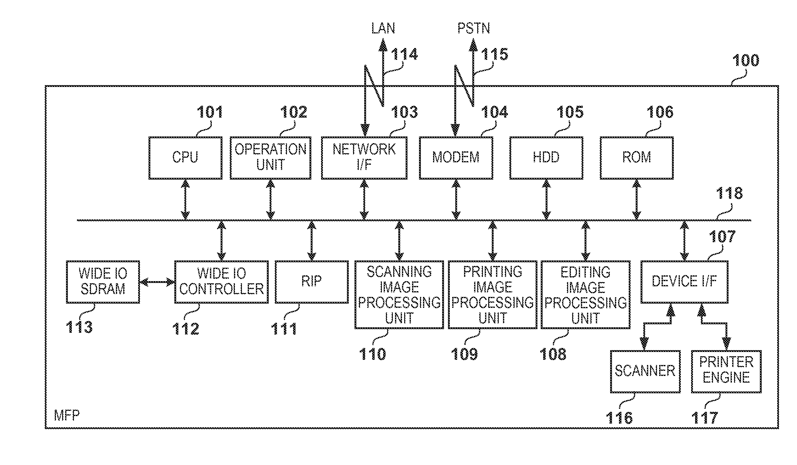
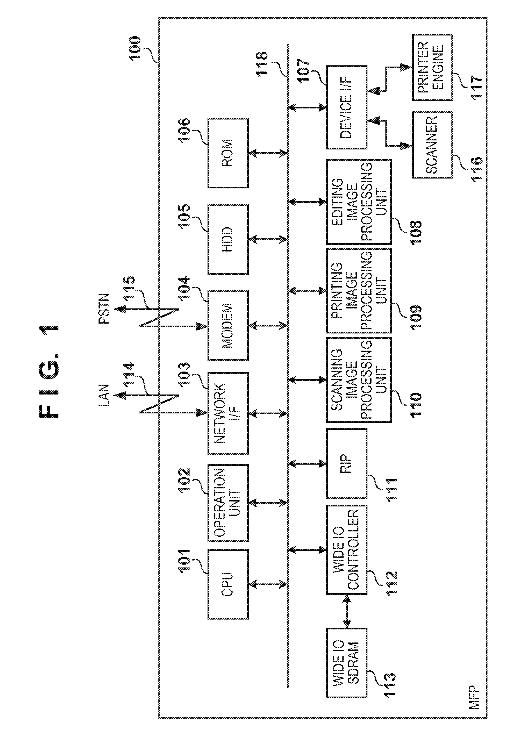
[0026]FIG. 1 is a block diagram showing an overall configuration of an MFP (a digital Multi-Function Peripheral) according no the first embodiment of the present invention.

[0027]An MFP 100 has a scanner 116 that is an image input device, and a printer engine 117 that is an image output device, and these are connected to a system bus 118 via a device interface (I / F) 107. The MFP 100 can perform scanning of an original image using the scanner 116, and printing using the printer engine 117, under control of the CPU 101. Also, the MFP 100 is connected to a LAN 114 and a public switched telephone network (PSTN) 115, and can input and output image data and device information regarding an external device connected to the LAN or the PSTN via the LAN 114 and the PSTN 115.

[0028]A CPU 101 controls the operation of this MFP 100 by executing a program loaded from an HDD 105 to a wide IO SDRAM 113 by a boot program stored in a ROM 106. An operation unit 102 has an input unit such as a touch panel...

second embodiment

[0057]Next, a second embodiment of the present invention will be described. When using multiple areas for storing an application program for one job, for every job to be executed by an MFP 100, the application program for executing that job is doubly loaded to two channels, for example. Furthermore, work areas are reserved for these channels. This doubles the amount of necessary memory resources compared to the conventional technology. In consideration of this, it is possible to doubly load only applications that correspond to jobs having a high execution frequency, or to jobs whose execution is accompanied by large temperature increases. Additionally, when there is little free space in the memory, it is possible to reduce the number of doubly-loaded applications.

[0058]In the second embodiment, an example will be described in which an application to be doubly-loaded is decided upon in accordance with the amount of free memory space, in the MFP 100 that has a print function, a scan f...


PUM


Abstract

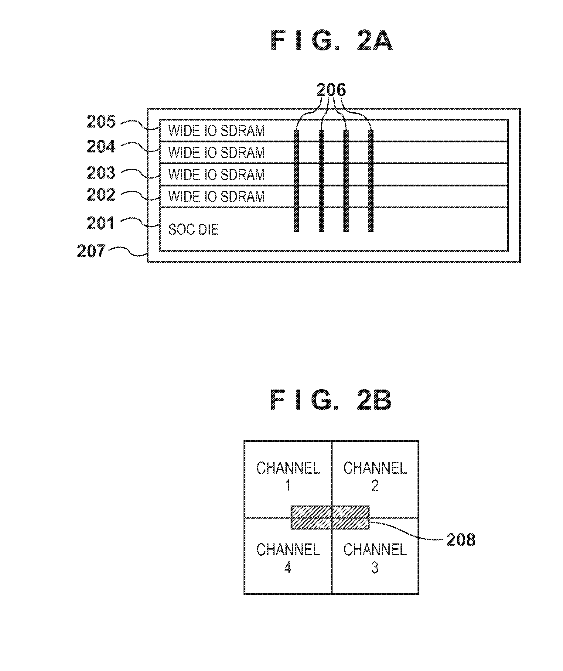
An information processing apparatus according to one aspect of the present invention includes a wide IO memory device stacked on an SoC die that includes a CPU, acquires temperature information of multiple memories in the wide IO memory device, loads applications for executing separate functions to multiple memories, excluding the memory positioned above the circuit on the SoC die related to the function to be executed by the application, and, when the execution of the loaded application is instructed, executes the application loaded to the memory having a lower temperature that was acquired.

Description

BACKGROUND OF THE INVENTION[0001]1. Field of the Invention[0002]The present invention relates to an information processing apparatus including a wide IO memory device stacked on an SoC die that includes a CPU.[0003]2. Description of the Related Art[0004]In information processing apparatuses that include a CPU such as a microprocessor, a DRAM is often used for storage of data for executing an OS and various applications, and for temporary storage of data for executing image processing. The DRAM is connected to a CPU, an SoC (System on a Chip), or the like and used by them. Furthermore, in recent years, as functions have been added / enhanced in information processing apparatuses, the amount of memory bandwidth needed in DRAMs has increased. Because of this, the amount of memory bandwidth has been increased by raising the clock frequency during memory access, according to a standard such as DDR3 or DDR4. Furthermore, as another method, memory bandwidth is reserved by including multiple ...

Claims


Application Information

Patent Timeline
IPC IPC(8): H04N1/00G06F1/20
CPCG06F1/206H04N1/00912H04N1/00954H04N1/00978H04N2201/0094G11C7/04Y02D10/00G06F3/0602G11C11/34
Inventor KAMBEGAWA, MINORU
Owner CANON KK
Learn More