
Real-time wireless dynamic tire pressure sensor and energy harvesting system

a dynamic tire and sensor technology, applied in the direction of electric generator control, pedestrian/occupant safety arrangement, instruments, etc., can solve the problems of ambient noise preventing detection, and achieve the effects of increasing output power density, constant and steady power, and high permeability

Active Publication Date: 2014-03-13
NORTHEASTERN UNIV
View PDF9 Cites 88 Cited by
  • Summary
  • Abstract
  • Description
  • Claims
  • Application Information

AI Technical Summary

Benefits of technology

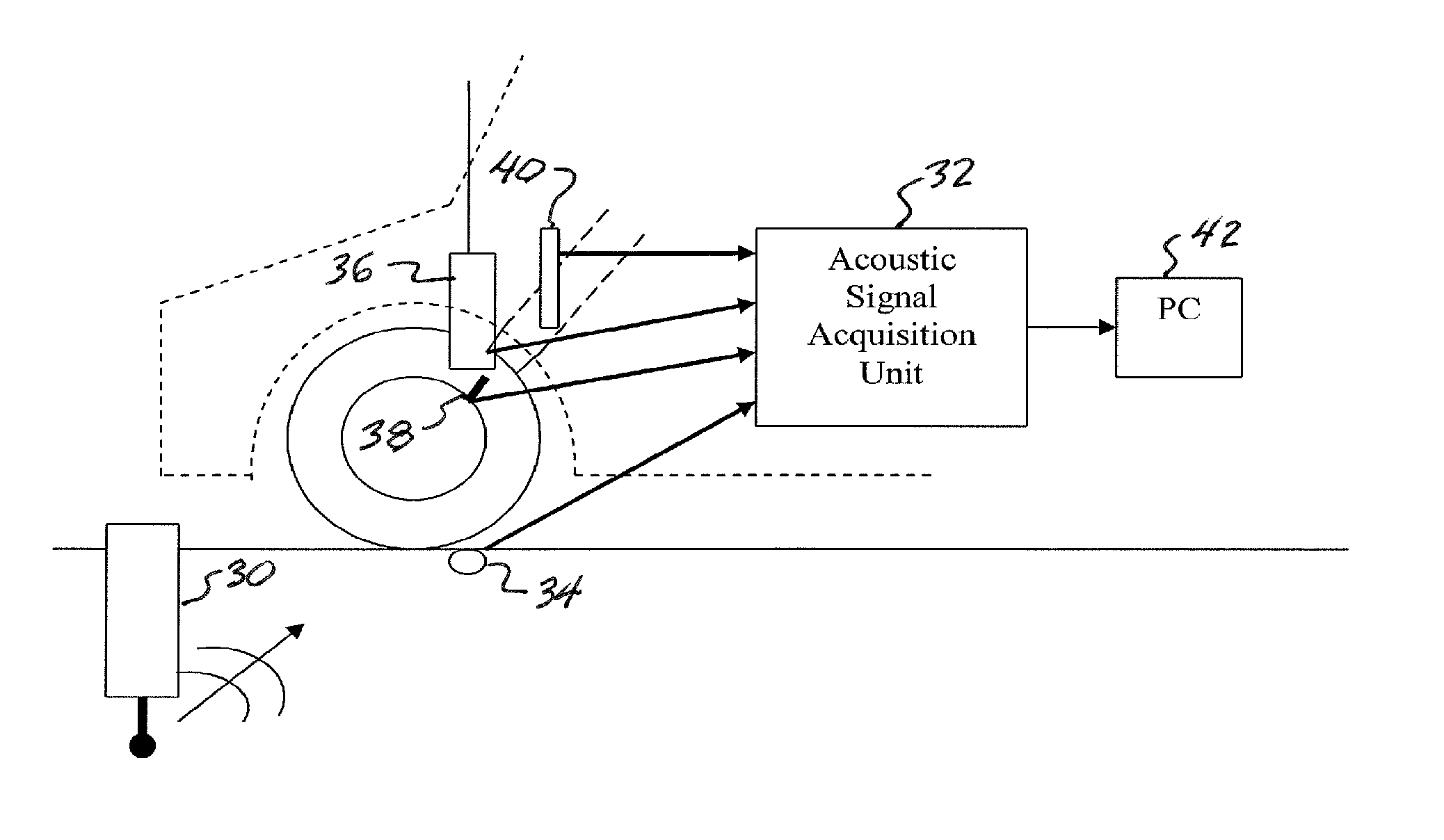
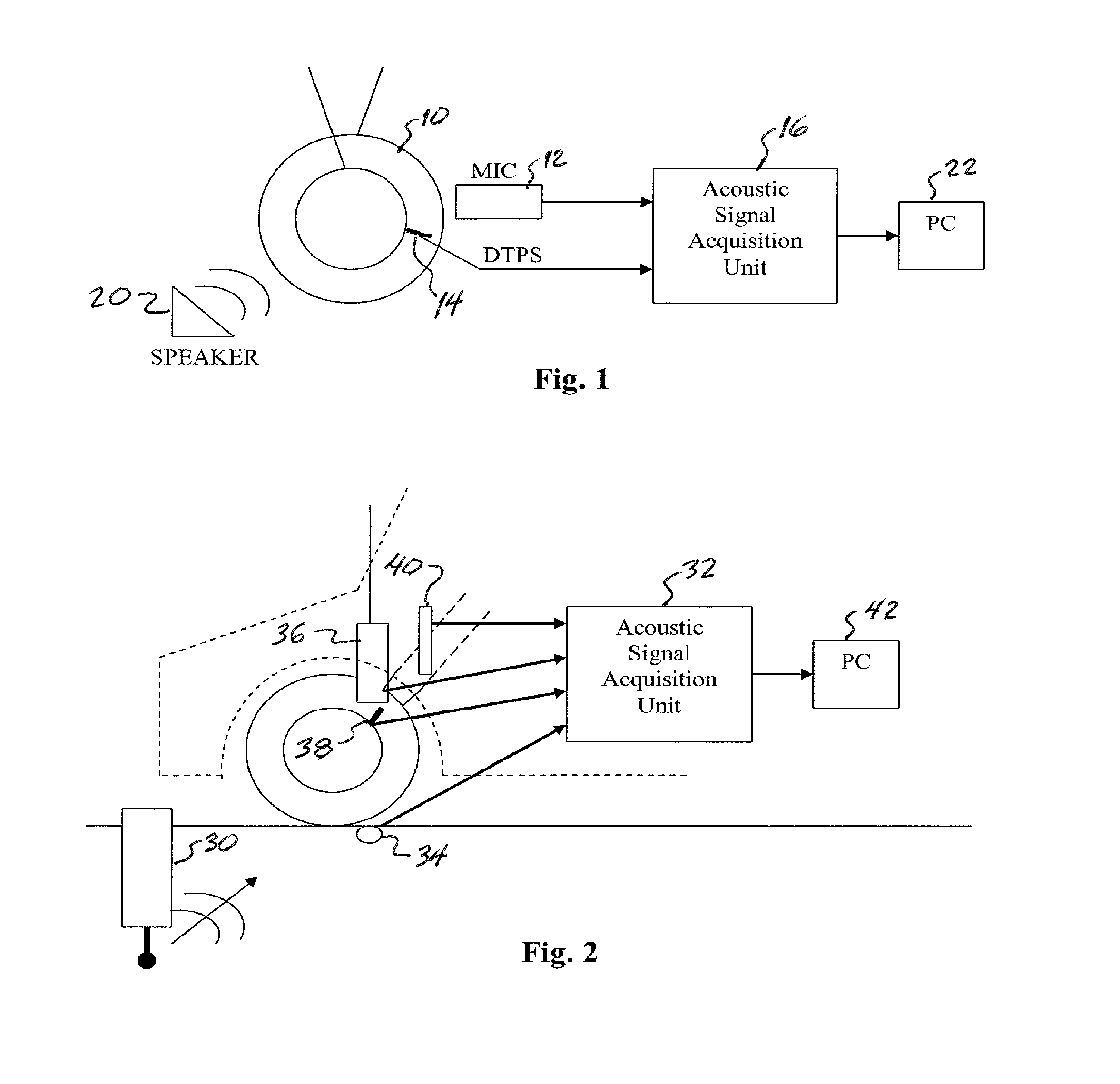
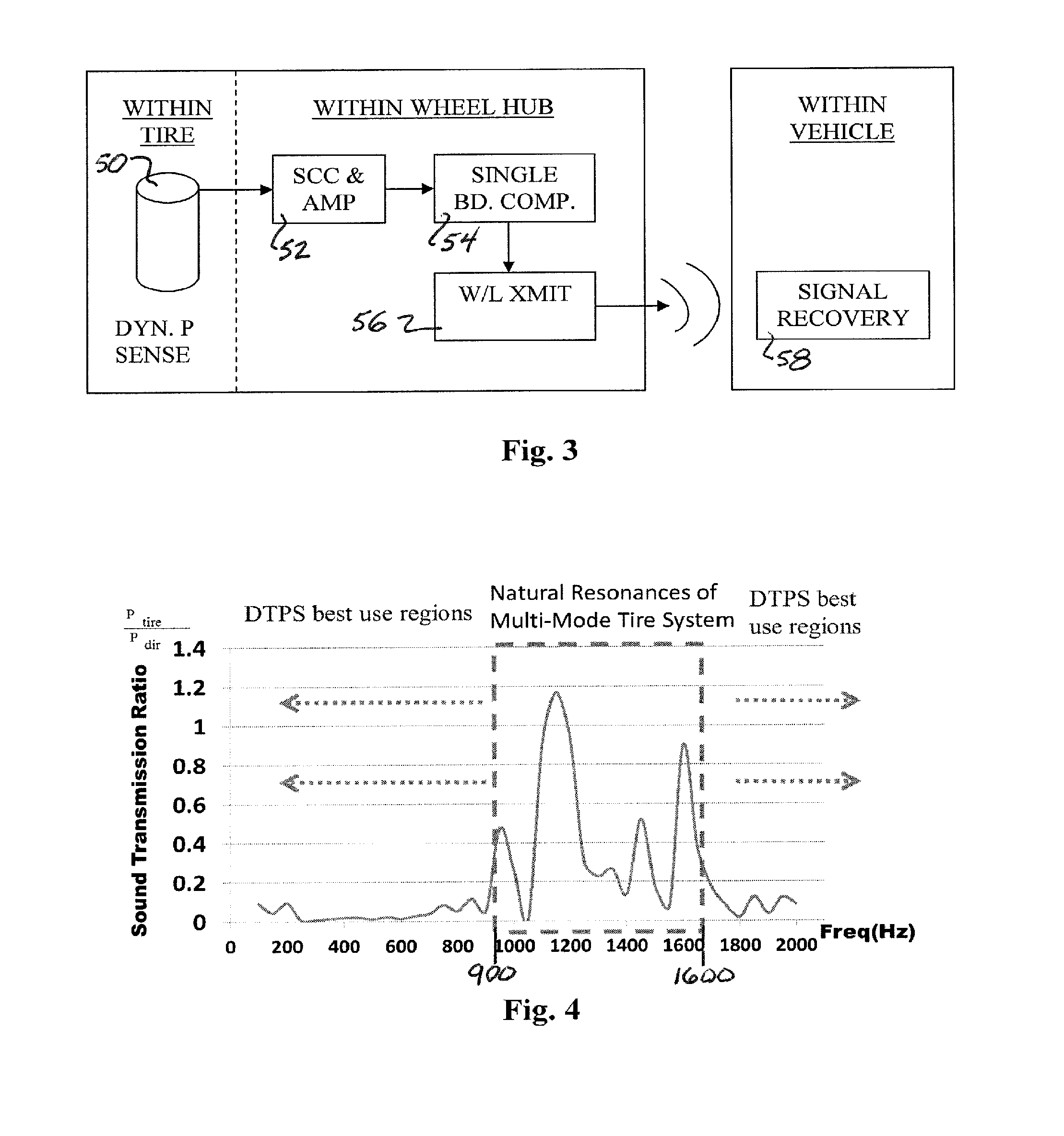
The patent describes a non-destructive and non-contact acoustic sensing technique for inspecting road and bridge deck conditions with vehicles running at normal speed without delaying or stopping other traffic. The technique uses a real-time dynamic tire pressure sensor (DIPS) placed inside the tire to measure dynamic pressure change inside the tire. The DIPS is able to detect surface and subsurface conditions, including potholes and cracks, and can also map roadway condition information with precision. The data collected by the DIPS is powered by a rotating energy harvester, which can power electronic sensors and wireless sensor networks, such as a TPMS. The energy harvester design is based on magnetostatic coupling between a stationary circular-arc hard magnet array and rotating magnetic solenoids, which switch the flux inside the solenoids during relative motion between the magnet array and the magnetic solenoids. The patent demonstrates the feasibility and applicability of the DIPS and energy harvester designs for fast inspection of road and bridge deck conditions.

Problems solved by technology

Aside from the obvious risk of transducer impact with the ground, there is a risk that the ambient noise would prevent the detection of acoustic signals from the tire-road interface and surface waves that propagate in the road.

Method used


Image

  • Real-time wireless dynamic tire pressure sensor and energy harvesting system
  • Real-time wireless dynamic tire pressure sensor and energy harvesting system
  • Real-time wireless dynamic tire pressure sensor and energy harvesting system

Examples


Embodiment Construction

[0046]Different acoustic and surface waves are generated at specific frequencies and amplitudes while a vehicle is traveling on varying road surfaces. These waves depend in part on the material properties of the road structure. The atmospheric acoustic field between the vehicle chassis and the road is also complex. Acoustic sources include aerodynamic effects, vehicle body vibration, ground vibration, direct radiation from the tire-road interface, and ambient noise due to other vehicles or acoustic sources.

[0047]Specifically, there are five distinct wave types that can be coupled to form acoustic waves within a subject vehicle tire due to complex interactions of the tire with the road surface. These different effects on the tire are: 1) direct surface wave from other tires or vehicles passing on the roadway nearby; 2) the acoustic wave from the interaction of the subject tire rolling on the roadway; 3) tire vibration (elastic) from, for example, axle vibration, or own tire excitatio...


PUM


Abstract

An instantaneous / real-time wireless dynamic tire pressure sensor (DTPS) for characterizing pavement qualities and for detecting surface and subsurface pavement defects under normal driving conditions. Signal processing provides quantitative assessment of surface conditions. DTPS includes a vehicle tire valve stem-mounted pressure sensor and wheel hub-mounted signal conditioning, amplification, and transmitting circuitry. A signal processing computer within the vehicle is wirelessly coupled to the hub-mounted circuitry. Tire pressure changes caused by ground vibration excitation from the interaction between the tire and pavement at normal driving speeds are detected. When acoustic radiation from a surface wave is significantly stronger than acoustic noise, subsurface information can be extracted. An energy harvester based on strong magnetostatic coupling between a high permeability core solenoid, fixed proximate a vehicle wheel, and a bias magnet array, fixedly mounted in conjunction with a dust shield, can provide power the DIPS.

Description

CROSS REFERENCE TO RELATED APPLICATIONS[0001]This application claims priority to and is a continuation of International Application No. PCT / US2012 / 038842 filed May 21, 2012, entitled “REAL-TIME WIRELESS DYNAMIC TIRE PRESSURE SENSOR AND ENERGY HARVESTING SYSTEM,” which claims the priority of U.S. Provisional Application No. 61 / 488,399 filed May 20, 2011, entitled “REAL-TIME WIRELESS DYNAMIC TIRE PRESSURE SENSOR (DTPS),” and U.S. Provisional Patent Application No. 61 / 488,407 filed May 20, 2011, entitled “WIRELESS ENERGY HARVESTING SYSTEM FOR REAL-TIME PRESSURE MONITORING SYSTEM.” The aforementioned related applications are hereby incorporated by reference in their entirety.STATEMENT REGARDING FEDERALLY SPONSORED RESEARCH OR DEVELOPMENT[0002]The research leading to this invention was carried out with U.S. Government support provided under a grant from the National Institute of Standards and Technology (NIST) Technology Innovation Program (TIP), Grant No. 70NANB9H9012. The U.S. Governme...

Claims


Application Information

Patent Timeline
Patent Type & Authority Applications(United States)
IPC IPC(8): B60C23/02H02J7/34H02K7/18
CPCB60C23/02H02J7/34H02K7/1892B60W40/06B60C23/0469B60C23/0486B60C23/041B60R2021/01304B60R2021/01308B60R2021/01306B60C23/0474B60C23/0494G01D5/12G01N29/041
Inventor WANG, MINGWANG, QIMCDANIELS, GREGORY J.SUN, NIAN X.
Owner NORTHEASTERN UNIV
Learn More