Electroslag and electrogas repair of superalloy components

a superalloy and component technology, applied in the direction of blade accessories, waterborne vessels, machines/engines, etc., can solve the problems of difficult structural welding, difficult structural repair or new fabrication of nickel and cobalt based superalloy materials used to manufacture turbine components, and blades that are susceptible to solidification, so as to reduce the scrap rate of damaged components

Active Publication Date: 2014-02-13
SIEMENS ENERGY INC
View PDF6 Cites 8 Cited by
  • Summary
  • Abstract
  • Description
  • Claims
  • Application Information

AI Technical Summary

Benefits of technology

[0013]Another object of the present invention is to increase the likelihood of performing successful structural repair of superalloy component castings, such as turbine vanes and blades, so that damaged component scrap rates can be reduced.
[0014]Yet another object of the p

Problems solved by technology

Structural repair or new fabrication of nickel and cobalt based superalloy material that is used to manufacture turbine components, such as cast turbine blades, is challenging, due to the metallurgic properties of the finished blade material.
The finished turbine blade alloys are typically strengthened during post casting heat treatments which render them difficult to perform subsequent structural welding.
When a blade constructed of such a material is welded with filler metal of the same or similar alloy, the blade is susceptible to solidification (aka liquation) cracking within and proximate to the weld, and/or strain age (aka reheat) cracking during subsequent heat treatment processes intended to restore the superalloy original strength and other material properties comparable to a new component.
Alternative superalloy welding processes, including laser microcladding with chill fixtures, welding in so called “hot” boxes at elevated temperatures, and inertia friction we

Method used


Image

  • Electroslag and electrogas repair of superalloy components
  • Electroslag and electrogas repair of superalloy components
  • Electroslag and electrogas repair of superalloy components

Examples


Embodiment Construction

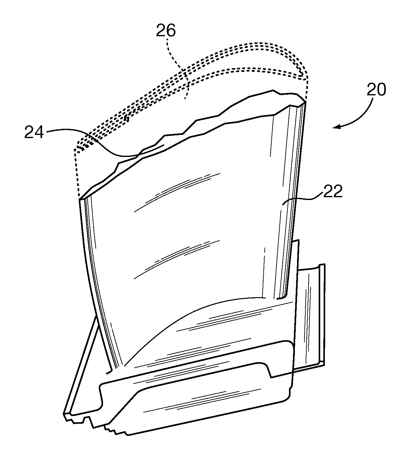
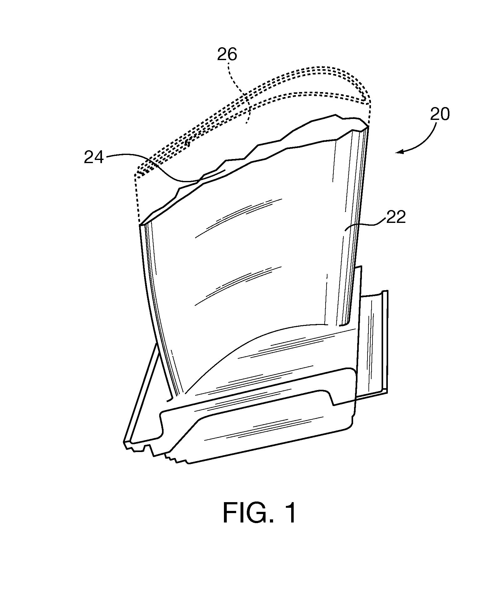
[0029]After considering the following description, those skilled in the art will clearly realize that the teachings of embodiments of the present invention can be readily utilized in fabricating or repairing superalloy component castings, such as turbine blades and vanes, by an electroslag or electrogas welding process that at least partially replicates the crystal structure of the original cast substrate in a cast-in-place substrate extension. The process re-melts the base substrate surface and grows it with new molten filler material. As the base substrate and the filler material solidify, the newly formed “re-cast” component has a directionally solidified uniaxial substrate extension portion that at least in part replicates the crystalline structure of the base substrate.

[0030]FIG. 1 shows an exemplary turbine blade superalloy casting 20 having a base substrate 22 and a service-degraded eroded surface 24. The dashed lines 26 show the blade 20 original profile that is to be replac...


PUM

PropertyMeasurementUnit
Structureaaaaaaaaaa
Electrical conductoraaaaaaaaaa
Crystal structureaaaaaaaaaa

Abstract

Superalloy component castings, such as turbine blades and vanes, are fabricated or repaired by an electroslag or electrogas welding process that at least partially replicates the crystal structure of the original cast substrate in a cast-in-place substrate extension. The process re-melts the base substrate surface and grows it with new molten filler material. As the base substrate and the filler material solidify, the newly formed “re-cast” component has a directionally solidified uniaxial substrate extension portion that at least in part replicates the crystalline structure of the base substrate. The “re-cast” component can be fabricated with a unified single crystal structure, including the extension portion. In other applications, a substrate extension can replicate a directionally solidified uniaxial crystal structure of an original base substrate casting. Polycrystalline substrate base structures can be re-cast with a substrate extension that replicates base substrate crystals that are most parallel to the uniaxial casting direction.

Description

BACKGROUND OF THE DISCLOSURE[0001]1. Field of the Invention[0002]The invention relates to repair of service-degraded superalloy component castings, such as turbine blades and vanes. More particularly the invention relates to repair or new fabrication of superalloy component castings by an electroslag welding process that re-melts a base substrate casting surface and grows it within a pool of molten filler material. As the combined melted material solidifies it forms a cast-in-place substrate extension that at least partially replicates the original substrate casting's crystal structure.[0003]2. Description of the Prior Art[0004]“Structural” repair of service-degraded gas turbine or other superalloy component castings is commonly recognized as replacing damaged material with matching alloy material and achieving properties, such as strength, that are close to the original manufacture component specifications (e.g., at least seventy percent ultimate tensile strength of the original sp...

Claims


Application Information

Patent Timeline
IPC IPC(8): B22D27/02F01D5/14B22D25/06B32B15/01
CPCB22D19/10B23K9/038B23K9/042B23K25/005B23K2101/001B23P6/007F01D5/005F05D2230/80F05D2300/175Y10T428/12986
Inventor BRUCK, GERALD J.
Owner SIEMENS ENERGY INC
Why Eureka
Try Eureka