Optical information reproduction apparatus

Inactive Publication Date: 2014-01-30
HITACHI CONSUMER ELECTRONICS CORP
View PDF11 Cites 6 Cited by
  • Summary
  • Abstract
  • Description
  • Claims
  • Application Information

AI Technical Summary

Benefits of technology

The present invention provides a measure for reproducing information without deteriorating the signal-to-noise ratio (S / N ratio) in an optical disc reproduction apparatus using the Homodyne phase diversity detection method. The invention achieves this by setting the vertical resolution of the A / D converter to a value equal to or higher than 7 bits, which effectively suppresses the jitter increment caused by quantization noise and maximizes the amplification effect of the signal amplitude. Additionally, the invention includes an absolute value calculator in the anterior stage of the A / D converter to improve the effective vertical resolution with respect to the reproduced signal component. This allows for a necessary and sufficient vertical resolution to be always ensured without excessively increasing the cost of the apparatus. Overall, the invention improves the quality of the reproduced signal while reducing the impact of quantization noise.

Problems solved by technology

When realizing the multilayer recording layer, since the larger the number of recording layers becomes, the lower the intensity of the reflected light returning to the optical pickup becomes, the influence of the detection system noise such as amplifier noise increases, and the signal-to-noise ratio (S / N ratio) of the reproduced signal drops.
When increasing the data transfer rate, due to increase in the detection system noise caused by broadening the bandwidth of the reproduced signal, the S / N ratio of the reproduced signal drops.
As described above, since the multilayer structure and the increase in the data transfer rate cause the drop of the S / N ratio, it is obvious that it becomes difficult to keep the reliability of the data with the reproduction method in the related art.
In the A / D converter, the quantization noise is caused by the error due to the conversion of an analog value into a digital value.
The influence thereof becomes nonnegligible in the case in which the vertical resolution decreases, and thus, the S / N ratio of the reproduced signal is deteriorated.
However, since the improvement of the vertical resolution is associated with increase in circuit size of the A / D converter and decrease in operation speed thereof, the vertical resolution is determined to be a level necessary and sufficient to make the influence of the quantization noise negligible.
Therefore, according to FIG. 3B, in the case of the normal detection method of the related art, if the vertical resolution becomes equal to or lower than 5 bits, the S / N ratio of the reproduced signal is deteriorated due to the influence of the quantization noise.
Therefore, if the vertical resolution of the A / D converter is not sufficiently high, the S / N ratio of the differential signal after being digitalized is deteriorated due to the influence of the quantization noise, and thus, the S / N ratio of the reproduced signal generated from the differential signals is also deteriorated.
Therefore, even if the A / D converter with the vertical resolution of 8 bit is used, the vertical resolution of about 4.4 bit can only be obtained effectively.
Therefore, the S / N ratio of the reproduced signal is deteriorated due to the influence of the quantization noise, and it becomes unachievable to maximally obtain the amplification effect of the signal amplitude due to the Homodyne detection.

Method used


Image

  • Optical information reproduction apparatus
  • Optical information reproduction apparatus
  • Optical information reproduction apparatus

Examples


embodiment 1

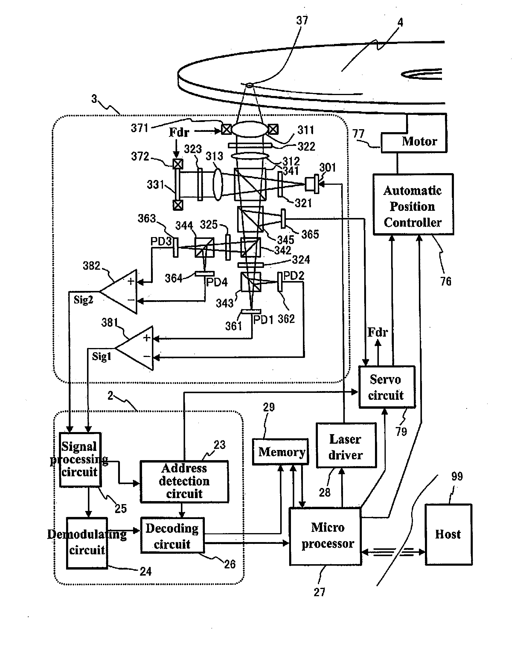
[0065]FIG. 4 shows a block diagram of an optical disc apparatus as an embodiment of the invention. The light emitted from a blue laser diode 301 with a wavelength of 405 nm mounted on an optical head 3 is transmitted through a first half wave plate 321 to thereby have the polarization direction rotated 45 degrees. The light with the polarization direction rotated is split by a first polarization beam splitter 341 into two linearly-polarized lights perpendicular to each other. The light (reproduction light) with one of the polarized lights is reflected, and is then collimated by a first collimator lens 312 into a parallel light, then transmitted through a first quarter plate 322 to thereby be converted into circularly-polarized light, then collected by an objective lens 311 with an NA of 0.85, and then an optical disc 4 is irradiated with the light. The reflected light (hereinafter referred to as a signal light) from the optical disc 4 is restored again to the parallel light by the o...

embodiment 2

[0071]FIG. 6 is a flowchart showing a procedure of determining the vertical resolution of the A / D converters 505 and 506 in EMBODIMENT 1 described above. As an overall flow, the vertical resolution RRF0 necessary and sufficient for the case of the normal detection is obtained in the steps S601 through S603, the increment ΔR of the vertical resolution is determined in the step S604, and the vertical resolution R in the case of the Homodyne phase diversity detection is determined in the step S605 based on RRF0 and ΔR.

Step S601:

[0072]FIG. 12 is a diagram showing a signal processing circuit used for obtaining the necessary and sufficient vertical resolution in the case of the normal detection. The reference symbol Sig0 denotes the reproduced signal obtained using a normal detector, which does not use the Homodyne phase diversity detection. The reproduced signal Sig0 is obtained by, for example, using a disc medium of a type with a single recording layer so that the sufficient S / N ratio ...

embodiment 3

[0081]FIG. 7 is a diagram showing a configuration of a signal processing circuit added with gain / offset adjustor circuits for applying the gain / offset to the two differential signals in the anterior stage of the A / D converters, respectively, as another embodiment of the signal processing circuit block.

[0082]As is pointed out in Document 1 or Document 2, in the case in which imbalance in amplitude between the two differential signals exists, and in the case in which an offset exists in each of the differential signals, the stable reproduced signal independent of the phase difference between the signal light and the reference light fails to be obtained even if the calculation expressed by the formula (7) is performed. According to the present embodiment, by performing an adjustment so that the amplitudes of the two differential signals become equal to each other, and the offset of each of the two differential signals vanishes using the signal adjustors 501, 502 added in the anterior s...


PUM


Abstract

In the optical information reproduction apparatus using Homodyne phase diversity detection, the S / N ratio of a reproduced signal is deteriorated due to the influence of a quantization noise generated in an A / D converter for digitalizing a differential signal. The optical information reproduction apparatus is arranged to have the A / D converter for digitalizing the differential signal having a vertical resolution equal to or higher than 9 bits.

Description

CLAIM OF PRIORITY[0001]The present application claims priority from Japanese patent application JP 2012-167926 filed on Jul. 30, 2012, the content of which is hereby incorporated by reference into this application.BACKGROUND OF THE INVENTION[0002]1. Field of the Invention[0003]The present invention relates to an S / N ratio improvement technology of a reproduced signal in an optical disc reproduction apparatus.[0004]2. Description of the Related Art[0005]The recording capacity of an optical disc has been improved from the Compact Disc (CD) up to the Blu-ray Disc™ (BD) through the Digital Versatile Disc (DVD) due to miniaturization of the optical spot achieved by decrease in the wavelength of the light source and increase in the numerical aperture of the objective lens. However, since the optical spot size has nearly reached a limit in the BD using the blue light source and the high numerical aperture objective lens, a multilayer structure for increasing the number of recording layers ...

Claims


Application Information

Patent Timeline
IPC IPC(8): G11B20/10
CPCG11B20/10481G11B7/005G11B20/10009
Inventor KUROKAWA, TAKAHIROKIKUGAWA, ATSUSHI
Owner HITACHI CONSUMER ELECTRONICS CORP
Why Eureka
Try Eureka