
Optical black surface

a technology of optical black and black paint, applied in the field of materials, can solve the problems of black velvet paint subject to chipping, detrimental to the desirability of the product, organic coatings are restricted to low temperature applications, etc., and achieve the effect of superior optical black surfa

Inactive Publication Date: 2014-01-30
BUDLESKI WILLIAM FRANK
View PDF3 Cites 12 Cited by
  • Summary
  • Abstract
  • Description
  • Claims
  • Application Information

AI Technical Summary

Benefits of technology

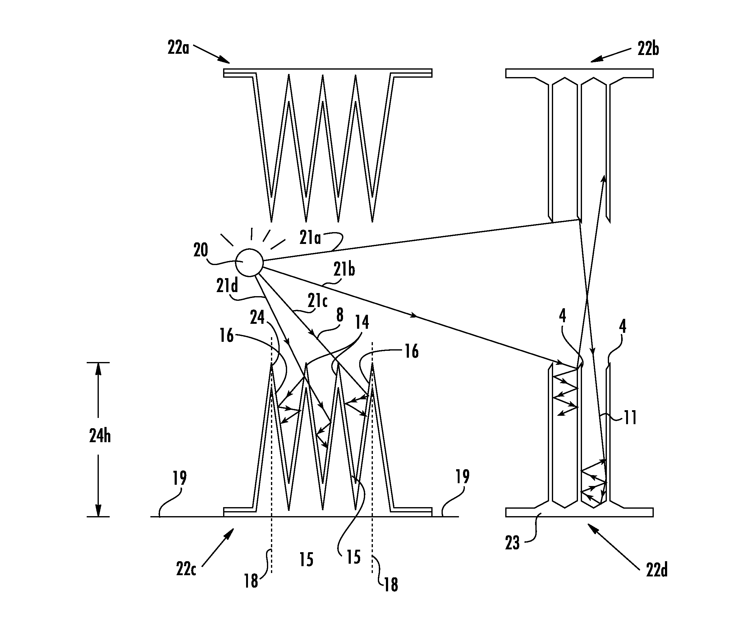
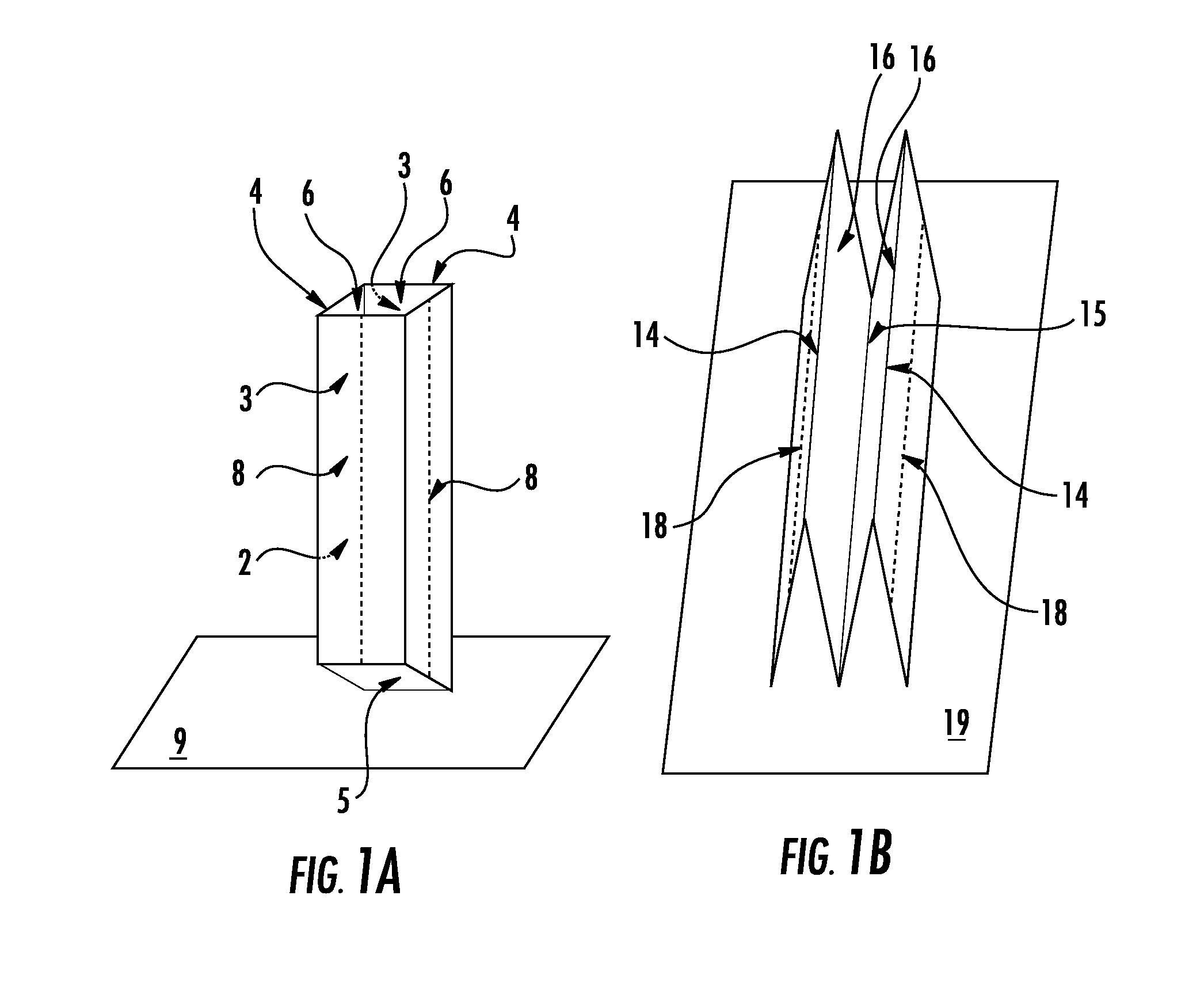
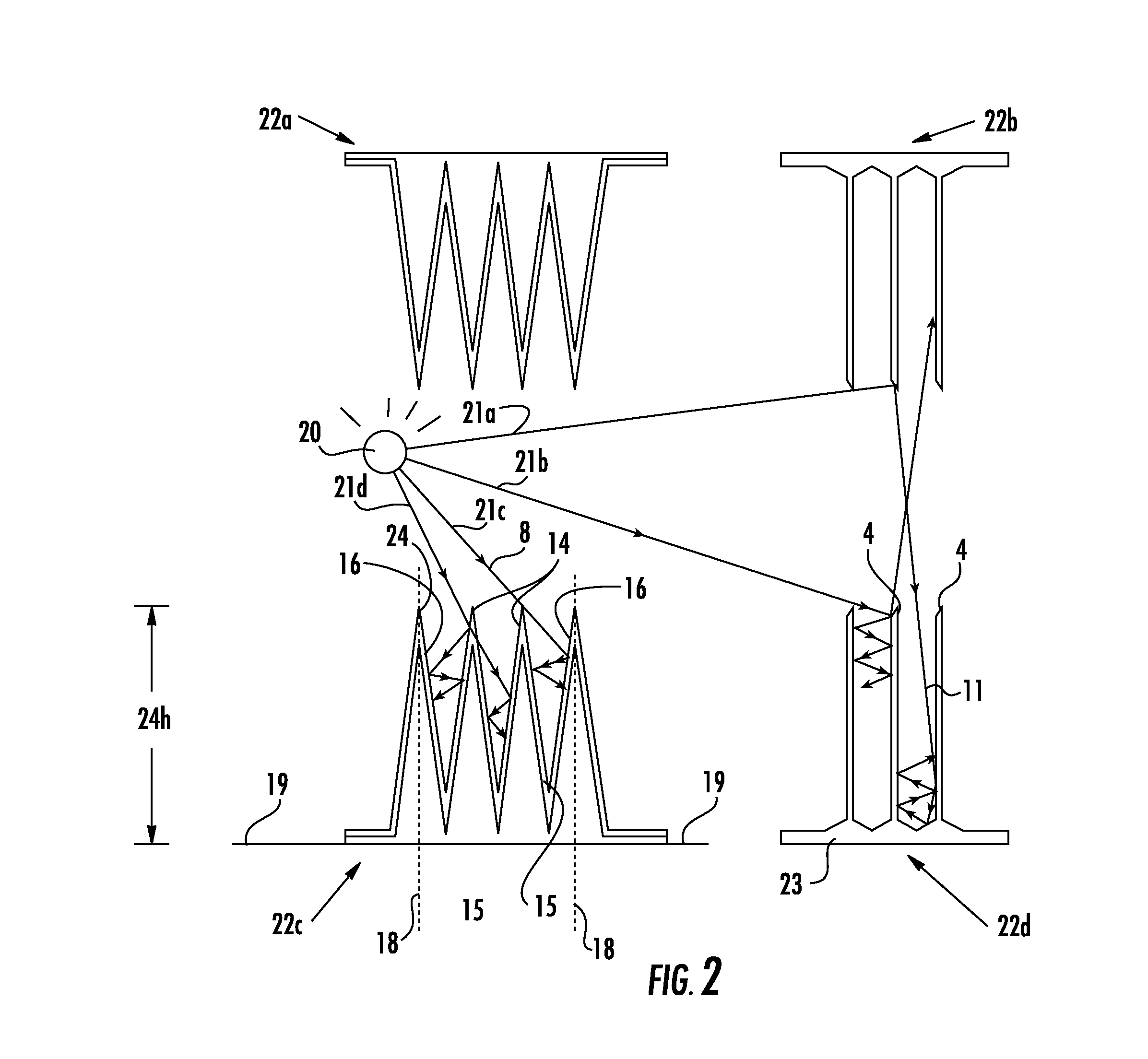
The invention creates a surface that has almost no light reflecting or absorbed, making it better at optical black. This is done by creating a matrix of cells that allows for no interference with the light.

Problems solved by technology

The 3M black velvet paint is subject to chipping after moderate temperature exposure and hydrocarbon outgassing, both of which detrimentally affect the desirability of the product.
In addition, because the organic binder will degrade at elevated temperatures, the organic coatings are restricted to low temperature applications.
Further, Parson's black, which contains a relatively high percentage of powdery carbon black, also lacks durability, being very easily removed from any surface on which it is applied.
The so-called high temperature black coatings are not entirely free from the problems of organic binders, since they basically comprise an organic material having inorganic components which are deposited as a residue.
Such a coating is inorganic and so will generally avoid the off-gassing problems associated with organic coatings, but such a coating process requires a large amount of expensive high temperature processing equipment, as well as processing steps, and if not properly heat treated, an organic residue may remain.
Further, in order to avoid the formation of heat scale, which is associated with ferrous alloys during the high temperature treatment step, e.g., on the inside of tubes which are being optically coated, a means is required to protect the inside of the tubes, such as an inert gas purge inside the tubes or the like treatment, which only adds to the complexity and expense of the process.
Further, while silicate coatings are inorganic, and thus do not suffer from the problems of organic coatings, they are known, depending upon the formulation, to suffer from problems of durability and moisture resistance.
However, such a coating would not be considered an optical black coating in that it would not have a sufficiently high solar absorptive, especially as compared to, e.g., 3M Nextel velvet black.

Method used


Image

  • Optical black surface
  • Optical black surface
  • Optical black surface

Examples


Embodiment Construction

[0034]While this invention is susceptible to embodiment in many different forms, there is shown in the drawings and will herein be described in detail specific embodiments, with the understanding that the present disclosure of such embodiments is to be considered as an example of the principles and not intended to limit the invention to the specific embodiments shown and described. In the description below, like reference numerals are used to describe the same, similar or corresponding parts in the several views of the drawings. This detailed description defines the meaning of the terms used herein and specifically describes embodiments in order for those skilled in the art to practice the invention.

[0035]The terms “a” or “an”, as used herein, are defined as one or as more than one. The term “plurality”, as used herein, is defined as two or as more than two. The term “another”, as used herein, is defined as at least a second or more. The terms “including” and / or “having”, as used he...


PUM

PropertyMeasurementUnit
Fractionaaaaaaaaaa
Fractionaaaaaaaaaa
Fractionaaaaaaaaaa

Abstract

The present invention relates to optical black material which absorbs light. The device has a plurality or matrix of cells, each cell by a specular and diffuse absorbing material generating mostly specular reflection which is captured.

Description

COPYRIGHT NOTICE [0001]A portion of the disclosure of this patent contains material that is subject to copyright protection. The copyright owner has no objection to the reproduction by anyone of the patent document or the patent disclosure as it appears in the Patent and Trademark Office patent files or records, but otherwise reserves all copyright rights whatsoever.BACKGROUND OF THE INVENTION [0002]1. Field of the Invention[0003]The present invention relates to a material having a light absorbing quality. In particular the present invention relates to material having the ability to have a high absorption of light shined on it.[0004]2. Description of Related Art[0005]Optical coatings and surfaces are known and are used in instances where low light reflectivity, or conversely high light absorption, is required, that is, surfaces which absorb a substantial portion of the electromagnetic radiation, especially in the solar spectrum, to which they are exposed. Historically, the highest a...

Claims


Application Information

Patent Timeline
IPC IPC(8): G02B1/10
CPCG02B1/11G02B5/003
Inventor BUDLESKI, WILLIAM FRANK
Owner BUDLESKI WILLIAM FRANK
Learn More