
Method and apparatus for precise seletion and extraction of a focused component in isoelectric focusing performed in micro-channels

a microchannel and focused component technology, applied in the field of separation and precise selection and extraction of components of analyte mixtures, can solve the problems of unavoidable component zone broadening, cross-contamination of closely migrating peaks, and inability to achieve more conventional separatory methods

Active Publication Date: 2014-01-23
PROTEINSIMPLE
View PDF1 Cites 2 Cited by
  • Summary
  • Abstract
  • Description
  • Claims
  • Application Information

AI Technical Summary

Benefits of technology

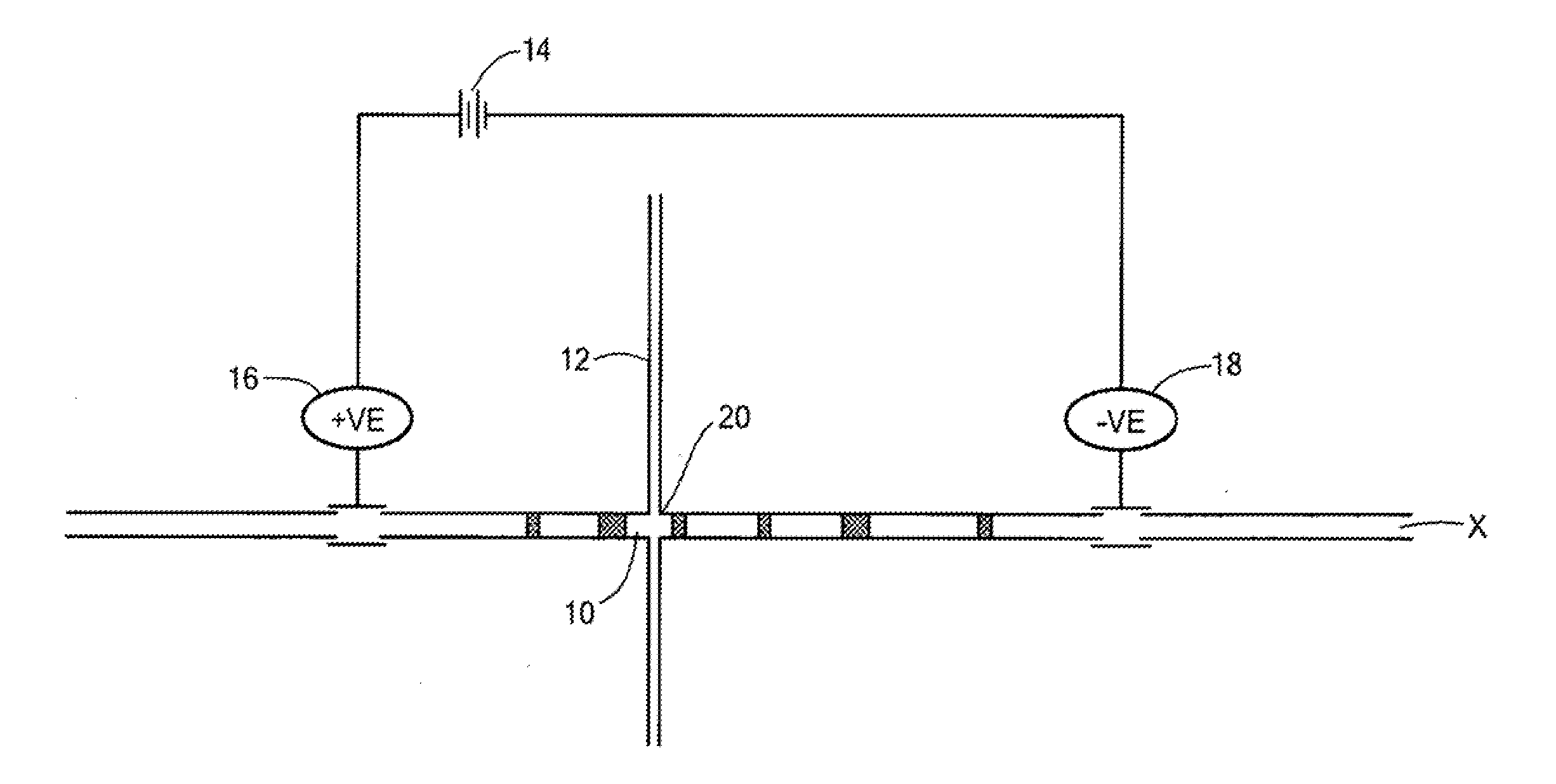
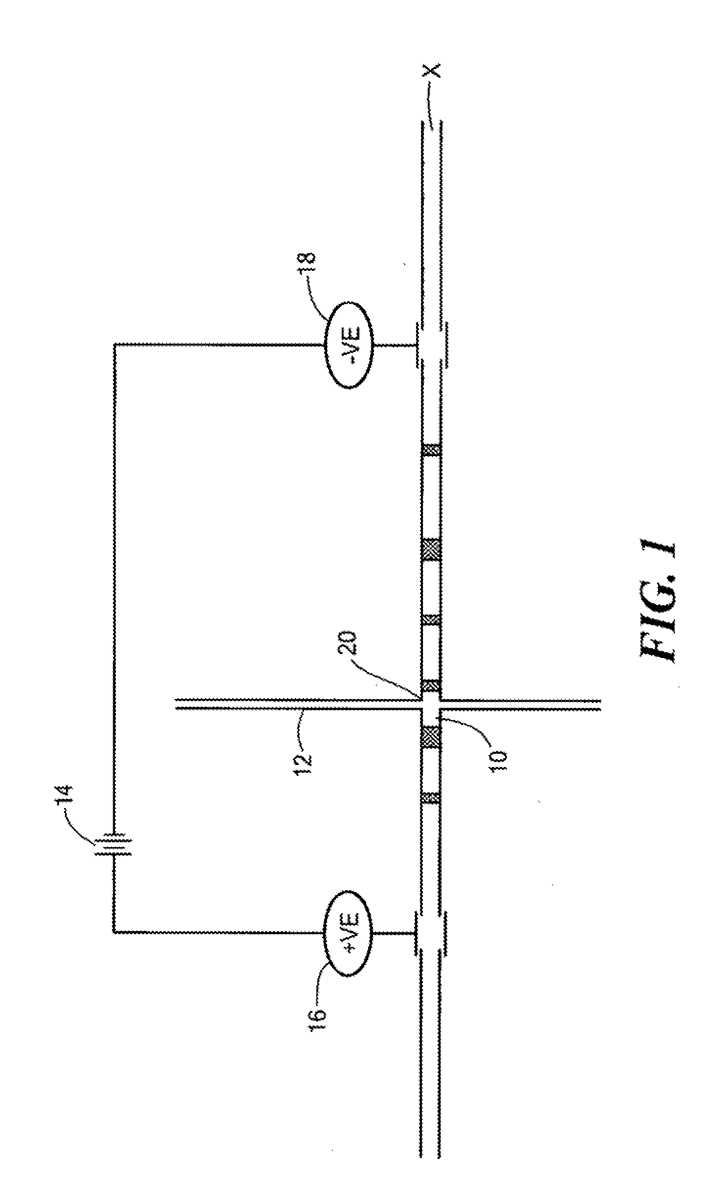
The invention is about an apparatus that can separate and detect components of a sample using a special technique called cIEF. The apparatus has a unique design that allows for real-time imaging analysis of the separation process. It can select specific components and move them to the intersection of the separation and extraction channels for further analysis. Overall, this invention provides a more efficient and accurate way to separate and detect components of a sample.

Problems solved by technology

This is generally not possible with more conventional separatory methods, even high-performance liquid chromatography (HPLC).
Cross-contamination frequently occurs for closely migrating peaks due to the extremely narrow peak width and extremely small amount of eluant.
Even then, however, component zone broadening is unavoidable during the separation process for the reasons stated above.
To date, however, others have had limited success in achieving any high degree of precision in the selection and extraction of cIEF component zones, chiefly because of the following limitations to the operation of their devices: 1) mobilization flow is in one direction; 2) mobilization speed is pre-determined and generally fixed and 3) inability to visualize the entire separation zones and detect in real-time any zone-width distortion due to mobilization.
This mobilization step in cIEF requires extra time and distorts the focused peaks, making it difficult to collect pure peaks without cross-contamination when peaks focus in close proximity.
It has, accordingly, not been possible with existing microfluidic (capillary) electrophoretic devices for micro-preparative fraction collection to observe all of the separated peaks developed by electrophoresis, then select a particular peak of interest and mobilize the entire pattern of peaks, while maintaining or re-establishing the focus of the pattern to bring the selected peak to a separation / collection point.

Method used


Image

  • Method and apparatus for precise seletion and extraction of a focused component in isoelectric focusing performed in micro-channels
  • Method and apparatus for precise seletion and extraction of a focused component in isoelectric focusing performed in micro-channels
  • Method and apparatus for precise seletion and extraction of a focused component in isoelectric focusing performed in micro-channels

Examples


experimental examples

Example 1

[0058]An IMED having the structure shown in FIG. 3 was used to selectively extract different hemoglobin variants of a mixture. An imaged cIEF system (Model iCE280, Convergent Bioscience Ltd., Toronto, Canada) was used as the real-time, whole separation channel UV detection apparatus, and protein detection was achieved through UV absorption at 280 nm. An autosampler from Prince CE system (Prince. Technologies, Emmen, The Netherlands) was used for sample injection and fluid manipulation along the separation channel. Methyl cellulose (MC), horse heart myoblobin, human transferrin, and pH 3-10 Pharmalyte were obtained from Sigma (St Louse, Mo.). Hemoglobin control AFSC was obtained from Helena Laboratories (Beaumont, Tex.). HPLC grade water was from J. T. Baker (Phillipsburg, N.J.), and was used for all solutions. Sample mixture solution was prepared by mixing protein with 8% pH 3-10 Pharmalytes and 0.35% MC.

[0059]The extraction channel of the IMED was first filled with HPLC wa...

example 2

[0063]FIG. 5 shows the separation and extraction of Hemoglobin S in the IMED with the device according to FIG. 4. The pI difference between Hemoglobin F and S and between Hemoglobin S and C was about 0.1. It can be seen that the separation pattern was not affected significantly upon hemoglobin s extraction, while the peak area of Hemoglobin S was reduced following extraction.

example 3

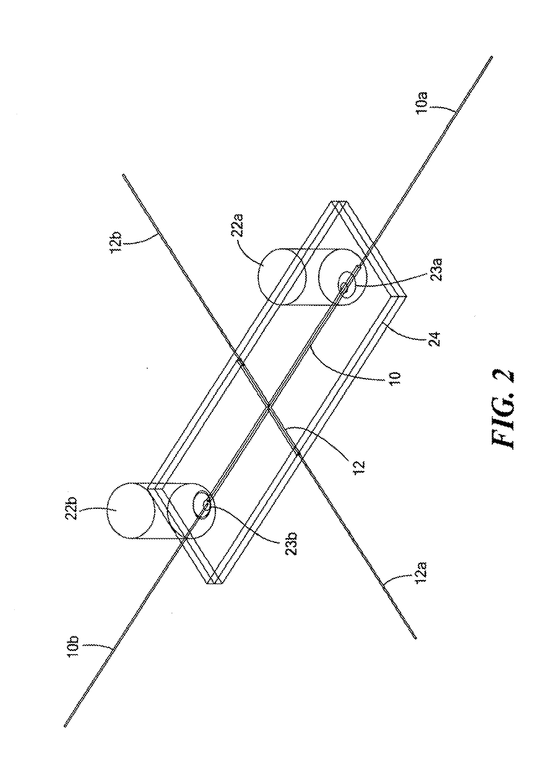
[0064]An IMED having the structure substantially represented in FIG. 2 was used to separate and selectively extract target protein component for off line MALDI-TOF characterization. FIG. 6 shows the cIEF electrophoregram of myoglobin and transferrine in 8% 5-8 Pharmalytes, 0.35% MC solution. It can be seen that the major component of transferrine and the major component of myoglobin were very well separated. Upon cIEF separation, the extracted individual protein was diluted to 100 μL in DI water, and 1 μL of this diluted sample was further diluted at either 1:2 or 1:10 ratio with 0.2% (v / v) trifluoroacetic acid in water. The further diluted protein sample of 1 μL was mixed with 1 μL of sinapinic acid (10 mg / mL), and 1 μL of this sample mixture was spotted for MALDI TOF MS (Voyager STR, Applied Biosystems, Foster City, Calif.).

[0065]FIGS. 7 and 8 shows the mass spectrograms of extracted myoglobin and transferrine. From the mass spectrogram, it can be seen that the presence of carrier...


PUM

PropertyMeasurementUnit
pore sizeaaaaaaaaaa
thicknessaaaaaaaaaa
semi-permeableaaaaaaaaaa

Abstract

An apparatus and method are disclosed for the precise selection and extraction of a selected analyte in a focused zone produced by isoelectric focusing performed in micro-channels. A cross-channel microfluidic device comprises a sample mixture introduction and separation channel and an extraction channel, which are in fluid communication with each other at a point of intersection. Means are provided for selectively moving the pattern of separated zones following cIEF to the intersection point, and means are provided for applying an extraction pressure to direct a single zone containing a selected analyte into and then out of the extraction channel for collection.

Description

CROSS REFERENCE TO RELATED APPLICATIONS[0001]This application claims the benefit under 35 U.S.C. §119(e) of U.S. Provisional Patent Application No. 60 / 819,390, filed on Jul. 10, 2006, the disclosure of which is incorporated by reference herein.STATEMENT REGARDING FEDERALLY SPONSORED RESEARCH OR DEVELOPMENT[0002]N / AFIELD OF THE INVENTION[0003]This invention relates to the separation and precise selection and extraction of components of an analyte mixture by means of liquid-phase capillary or micro-channel electrophoresis. The principal application of the invention is to facilitate the identification and characterization of the extracted component(s) through the subsequent use of micro-analytical techniques such as mass spectrometry.BACKGROUND OF THE INVENTION[0004]Capillary electrophoresis (CE) has been established as an important separation technique in bioanalytical chemistry. Separation and detection of very small amounts of biological samples, about pL-nL volumes, can be achieved...

Claims


Application Information

Patent Timeline
Patent Type & Authority Applications(United States)
IPC IPC(8): G01N27/447
CPCG01N27/44795B01L3/5027G01N1/40G01N27/44739G01N2001/4038
Inventor WU, JIAQIHUANG, TIEMINWATSON, ARTHUR H.
Owner PROTEINSIMPLE
Learn More