
Hard-coated member and its production method, and indexable rotary tool comprising it

a technology of hard coating and rotary tool, which is applied in the direction of manufacturing tools, superimposed coating process, transportation and packaging, etc., can solve the problems of insufficient adhesion of aluminum oxide film, insufficient adhesion of upper titanium carbonitride layer, and failure to have sufficient adhesion, etc., to achieve high hardness and wear resistance, and high adhesion

Active Publication Date: 2014-01-16
HITACHI TOOL ENG LTD
View PDF7 Cites 8 Cited by
  • Summary
  • Abstract
  • Description
  • Claims
  • Application Information

AI Technical Summary

Benefits of technology

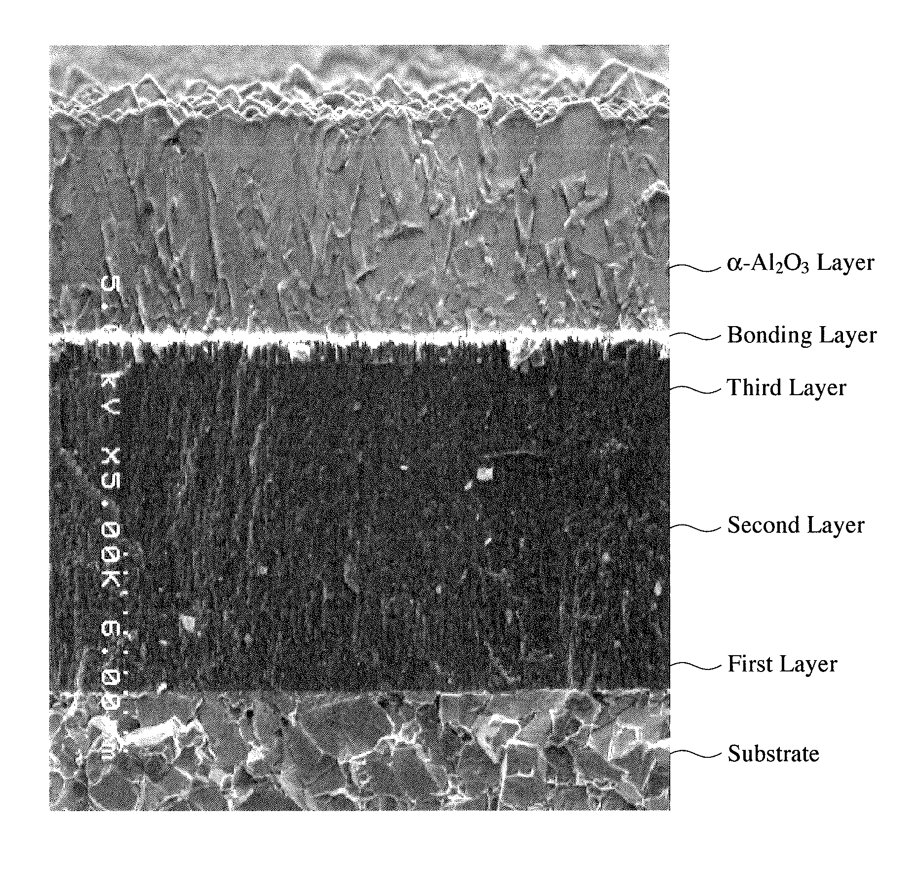
The present invention is about a hard-coated member that has a substrate made of cemented carbide or high-speed steel, and a hard coating that is formed on the substrate using a chemical vapor deposition method. The hard coating is made up of a titanium carbonitride layer that has three layers, each with a columnar crystal structure. The upper layer is located closest to the substrate. The technical effect of this invention is that it provides a hard-coated member that has superior mechanical properties and durability, making it useful in a variety of applications such as cutting tools, drill bits, and engine parts.

Problems solved by technology

However, it has been found that because the columnar crystal TiCN film is a single layer having a high carbon concentration, it has insufficient adhesion to the aluminum oxide film.
However, because the method described in JP 2005-212047 A provides the upper titanium carbonitride layer with a higher carbon concentration than that of the lower titanium carbonitride layer, the upper titanium carbonitride layer has insufficient adhesion to the Al2O3 film.
However, like JP 2005-212047 A, this surface-coated cutting tool comprises the carbon-rich TiCN film on the nitrogen-rich TiCN film, failing to have sufficient adhesion to the Al2O3 layer.
In addition, it has poor wear resistance and thus a short life, because of the lack of a layer corresponding to the second layer in the present invention.

Method used


Image

  • Hard-coated member and its production method, and indexable rotary tool comprising it
  • Hard-coated member and its production method, and indexable rotary tool comprising it
  • Hard-coated member and its production method, and indexable rotary tool comprising it

Examples


example 1

[0141](1) Formation of Hard Coating Comprising Titanium Carbonitride Layer, Bonding Layer and Oxide Layer

[0142]Cutting edge portions 21 of a turning insert substrate (TNMG160408) 20 made of cemented carbide comprising 6% by mass of Co, the balance being WC and inevitable impurities, which is schematically shown in FIGS. 3(a)-3(c), were honed by a diamond brush. Incidentally, 23 represents a land, and 24 represents a flank.

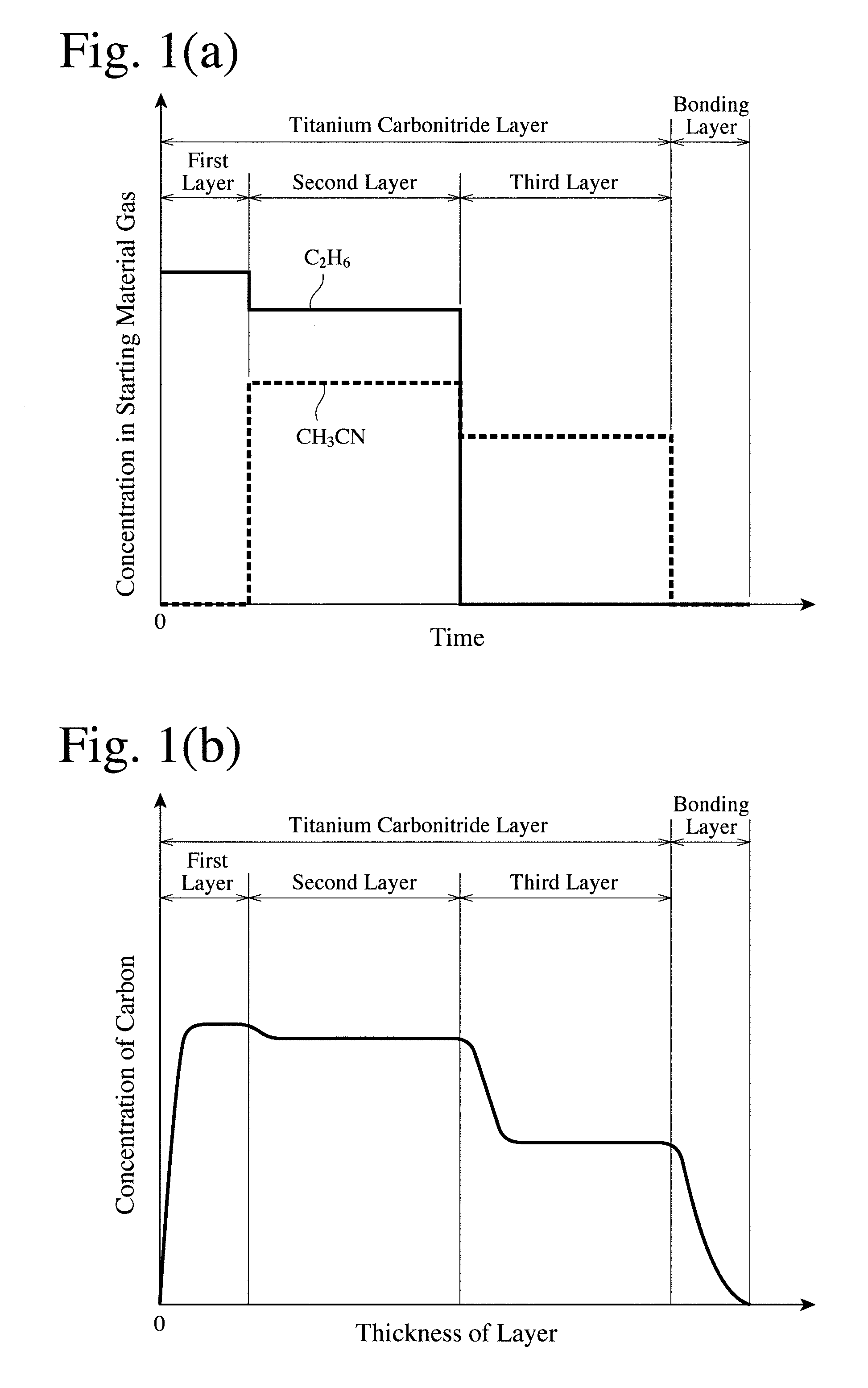
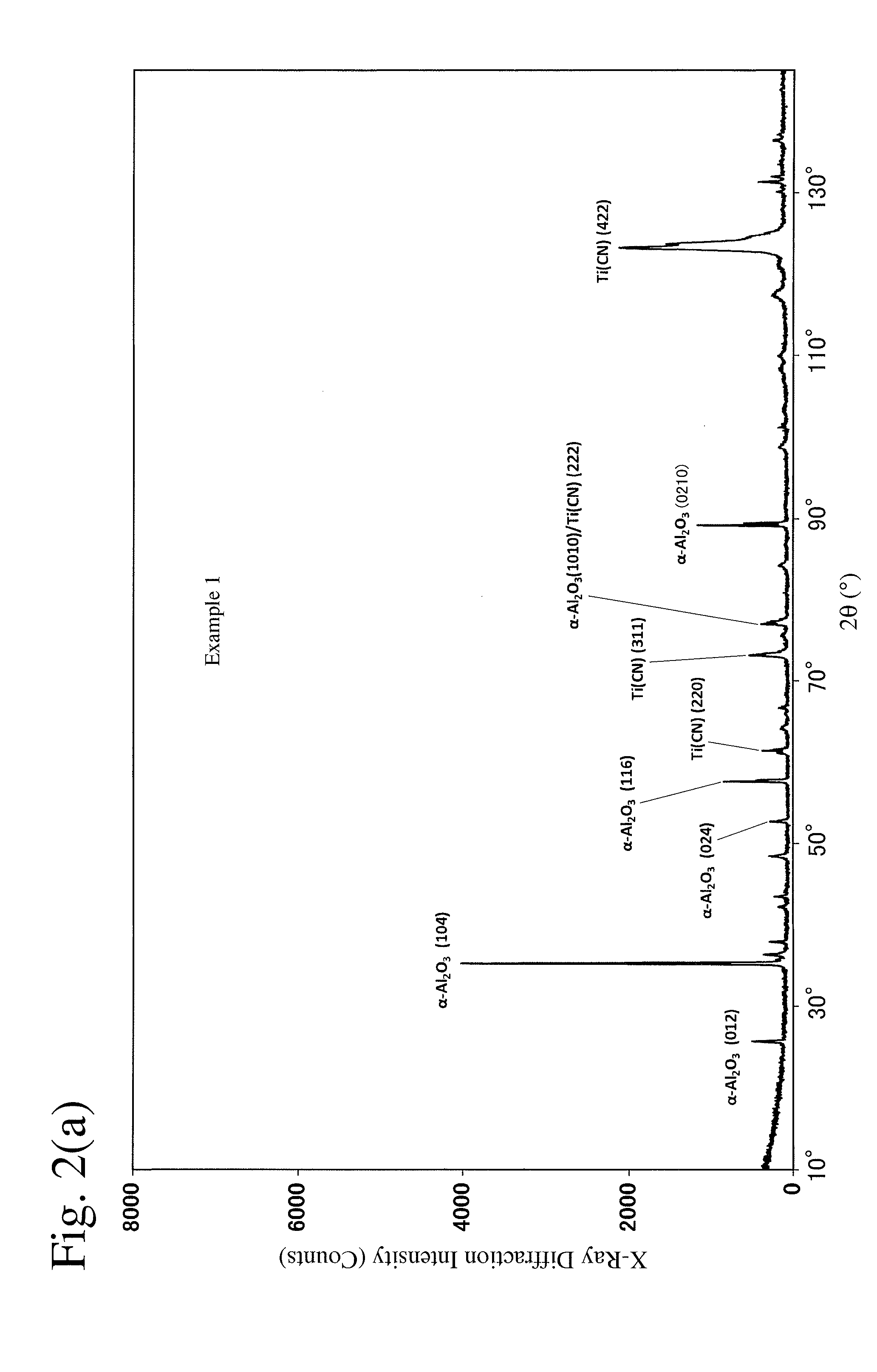
[0143]With this insert substrate (TNMG160408) disposed in a CVD chamber, the temperature in the CVD chamber was elevated to 850° C. while flowing an H2 gas. First, with a starting material gas at 850° C. and 10 kPa, which comprised 66.0% by volume of an H2 gas, 32.2% by volume of an N2 gas, 0.5% by volume of a TiCl4 gas, and 1.3% by volume of a C2H6 gas, supplied to the CVD chamber at a flow rate of 6100 ml / minute, a 0.5-μm-thick first layer was formed as a titanium carbonitride layer by a chemical vapor deposition method. With a starting material gas at 850° C. an...

examples 2-31

[0166]The titanium carbonitride layers, bonding layers and oxide layers of Examples 2-31 were formed in the same manner as in Example 1, except for changing the film-forming conditions of the first to third layers and the compositions of the bonding layers as shown in Tables 1-4, and their properties and performance were evaluated in the same manner as in Example 1. The concentration distributions of C and N in a thickness direction in the titanium carbonitride layer (first to third layers) of Example 2 are shown in FIG. 7.

example 32

[0172]After the first layer in the titanium carbonitride layer was formed on the same substrate with honed cutting edges as in Example 1 under the conditions shown in Table 11, an 8-μm-thick second layer having a composition of (TiZr)(CN) was continuously formed by supplying a starting material gas at 850° C. and 10 kPa, which comprised 80.3% by volume of an H2 gas, 15.0% by volume of an N2 gas, 1.5% by volume of a TiCl4 gas, 1.0% by volume of a CH3CN gas, 1.2% by volume of a C2H6 gas, and 1.0% by volume of a ZrCl4 gas, at a flow rate of 6700 ml / minute to the CVD chamber. A 2-μm-thick third layer having a composition of (TiZr)(CN) was then continuously formed by supplying a starting material gas at 850° C. and 10 kPa, which comprised 82.0% by volume of an H2 gas, 15.0% by volume of an N2 gas, 1.5% by volume of a TiCl4 gas, 0.5% by volume of a CH3CN gas, and 1.0% by volume of a ZrCl4 gas, at a flow rate of 6600 ml / minute to the CVD chamber. A bonding layer and an α-aluminum oxide fil...


PUM

PropertyMeasurementUnit
cross section diameteraaaaaaaaaa
thicknessaaaaaaaaaa
thicknessaaaaaaaaaa

Abstract

A hard-coated member comprising a substrate made of cemented carbide or high-speed steel and a titanium carbonitride layer formed on the substrate by a chemical vapor deposition method, the titanium carbonitride layer comprising first to third layers each having a columnar crystal structure in this order from the side of the substrate, the second layer being smaller than the first layer in carbon concentration, and the third layer being smaller than the second layer in carbon concentration, and an indexable rotary tool comprising it. The first layer is formed by using a starting material gas comprising a TiCl4 gas, an N2 gas, a C2-C5 hydrocarbon gas and an H2 gas, the second layer is formed by using a starting material gas comprising a TiCl4 gas, an N2 gas, an organic cyanide gas, a C2-C5 hydrocarbon gas, and an H2 gas, and the third layer is formed by using a starting material gas comprising a TiCl4 gas, an N2 gas, an organic cyanide gas, whose amount is smaller than in the second layer, and an H2 gas.

Description

FIELD OF THE INVENTION[0001]The present invention relates to a hard-coated member comprising a hard coating having high hardness and wear resistance as well as high adhesion to a substrate of cemented carbide or high-speed steel and an upper layer, a method for producing such a hard-coated member by a chemical vapor deposition method, and an indexable rotary tool comprising such a hard-coated member.BACKGROUND OF THE INVENTION[0002]Surface-coated cutting tools having single-layer or multi-layer hard coatings of TiC, TiN, TiCN, Al2O3, etc. on the surfaces of substrates made of cemented carbides, cermets, ceramics, etc. have been conventionally used for the cutting of metals, etc. Because such surface-coated cutting tools are used under increasingly severer conditions (for example, those subject to large shock such as heavy, intermittent cutting, etc.), desire is mounting on cutting tools having hard coatings durable to large shock.[0003]JP 2008-87150 A discloses a coated cutting tool...

Claims


Application Information

Patent Timeline
Patent Type & Authority Applications(United States)
IPC IPC(8): C23C16/36B05D5/00
CPCC23C16/36B05D5/00C23C16/029C23C16/403C23C16/45523C23C28/042C23C28/044C23C28/048C23C30/005Y10T428/24967Y10T428/24975Y10T428/25B23B27/14
Inventor FUKUNAGA, YUUZOHKUBOTA, KAZUYUKI
Owner HITACHI TOOL ENG LTD
Learn More