Heating system for heating heat-transfer oil usingboiler flue gas

a technology of heating system and boiler flue gas, which is applied in the direction of water feed control, heating type, automatic control of ignition, etc., can solve the problems of large waste of energy, low temperature corrosion generally occurs, and high corrosion of heating surfaces, so as to ensure the efficiency and output of the original boiler, reduce the temperature of the exhaust gas of the furnace, and improve the energy utilization efficiency

Inactive Publication Date: 2014-01-09
SHANGHAI FUBO ENVIRONMENTAL PROTECTION EQUIP
View PDF9 Cites 16 Cited by
  • Summary
  • Abstract
  • Description
  • Claims
  • Application Information

AI Technical Summary

Benefits of technology

[0019]Advantages of the invention are summarized below: the heating system of heat-transfer oil using the exhaust heat of boiler flue gas fully utilizes the exhaust heat of the flue gas. By changing the arrangement of the heating surfaces in the rear part of the boiler, the efficiency and the output of the original boiler are ensured, the exhaust gas temperature of the furnace is lowered, part of the exhaust heat of the flue gas is recycled, and the recycled heat energy is used to heat the heat carrier-heat-transfer oil which can be widely applied in petroleum, chemical, textile, printing and dyeing, rubber, leather, food, wood processing and many other industries. Furthermore, on the basis of preventing the devices where the flue gas passes through from dew-acid corrosion, the exhaust heat of the flue gas is recycled to the utmost, the utilization efficiency of the energy is improved, the efficiency of flue gas discharging from the furnace is improved, and the utilization types of the heat energy is various.

Problems solved by technology

When the temperature of the flue gas is lower than a certain degree, sulfur in the flue gas combines with the water vapor therein and is transformed into sulfuric acid which is corrosive to the heat transfer device.
Low temperature corrosion generally occurs in a cool end of the air pre-heat device and an economizer having a low feedwater temperature.
When the temperature of the heating surfaces is lower than a dewpoint of the flue gas, sulfuric acid resulting from the reaction between the water vapor in the flue gas and sulfur trioxide (accounting for a very small part of the sulfuric product produced from the combustion of the coal fuel) is condensed on the heating surfaces, thereby being heavily corrosive to the heating surfaces.
The exhaust temperature of a new boiler is generally 140° C., and after running for a certain period, the exhaust temperature achieves 160° C. The direct discharge of the flue gas results in a large waste of energy.

Method used


Image

  • Heating system for heating heat-transfer oil usingboiler flue gas
  • Heating system for heating heat-transfer oil usingboiler flue gas
  • Heating system for heating heat-transfer oil usingboiler flue gas

Examples


Embodiment Construction

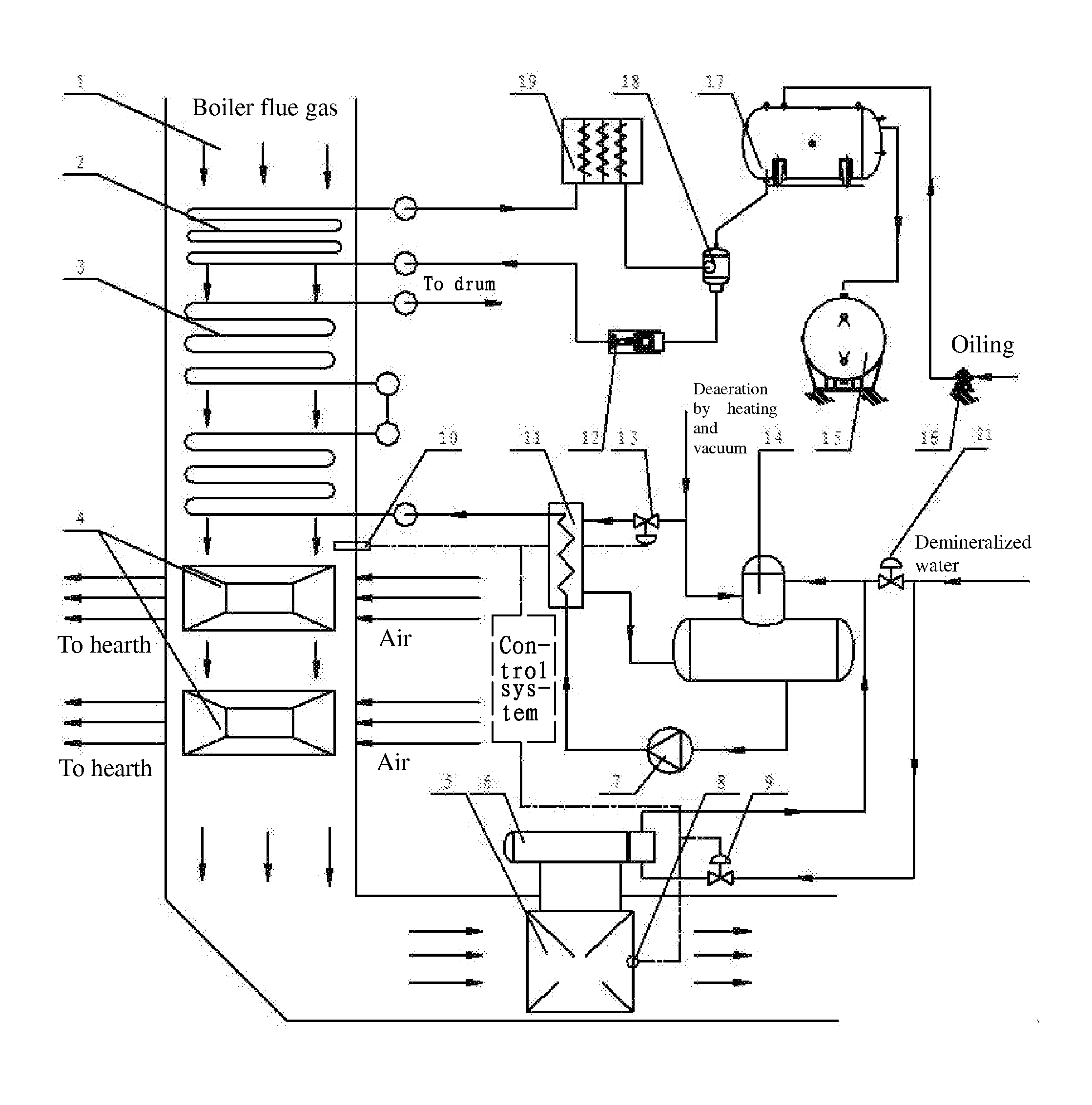
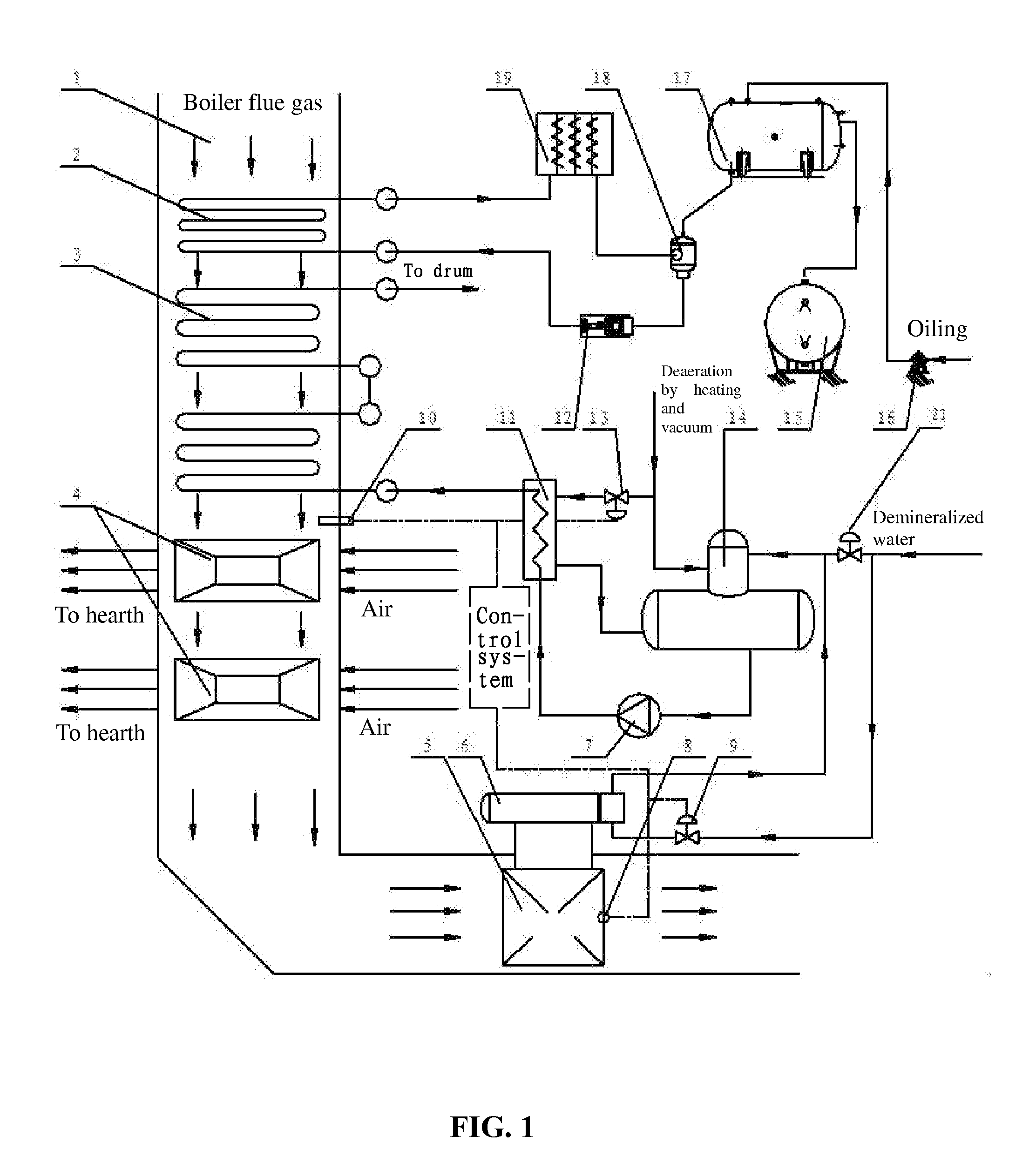
[0022]A heating system of heat-transfer oil using exhaust heat of flue gas from a boiler, the system comprises an economizer 3 and an air preheater 4 being disposed inside a flue 1 along a flow direction of the flue gas. The system further comprises a heat-transfer oil heater 2 disposed inside the flue 1 in front of the economizer 3. The heat-transfer oil heater 2 is connected to a heat consumption device 19 via a first circulating pipe. A circulating pump 12 is disposed on the first circulating pipe.

[0023]As shown in FIG. 1, the heat-transfer oil heater 2, the economizer 3, and the air preheater 4 are disposed inside the flue 1 along the flow direction of the flue gas. The heat-transfer oil heater 2 is connected to the heat consumption device 19 via the first circulating pipe. The circulating pump 12 is disposed on the first circulating pipe for driving the circulation of a heat carrier of the heat-transfer oil heater 2. In a rear part of the flue 1, part of the heat energy of the ...


PUM


Abstract

A heating system for heating heat-transfer oil using exhaust heat of boiler flue gas. The system includes: a flue, an economizer, an air preheater, and a heat-transfer oil heater. The economizer and the air preheater are disposed in the flue along the flow direction of the flue gas. The heat-transfer oil heater is disposed inside the flue in front of the economizer and is connected to a heat consumption device via a first circulating pipe. The circulating pipe is equipped with a circulating pump.

Description

CROSS-REFERENCE TO RELATED APPLICATIONS[0001]This application is a continuation-in-part of International Patent Application No. PCT / CN2011 / 080030 with an international filing date of Sep. 22, 2011, designating the United States, now pending, and further claims priority benefits to Chinese Patent Application No. 201120069052.6 filed Mar. 16, 2011. The contents of all of the aforementioned applications, including any intervening amendments thereto, are incorporated herein by reference. Inquiries from the public to applicants or assignees concerning this document or the related applications should be directed to: Matthias Scholl P.C., Attn.: Dr. Matthias Scholl Esq., 14781 Memorial Drive, Suite 1319, Houston, Tex. 77079.BACKGROUND OF THE INVENTION[0002]1. Field of the Invention[0003]The invention relates to absorption and utilization of waste heat from boiler flue gas, and more particularly to a heating system of heat-transfer oil using boiler flue gas.[0004]2. Description of the Relat...

Claims


Application Information

Patent Timeline
Patent Type & Authority Applications(United States)
IPC IPC(8): F24H1/12F24D7/00F22D5/00F22D1/38
CPCF24H1/125F22D1/38F24D7/00F22D5/00F22D1/36F22D1/50
Inventor QIAN, XUELVELIU, BING
Owner SHANGHAI FUBO ENVIRONMENTAL PROTECTION EQUIP
Why Eureka
Try Eureka