
Biochip and fabrication thereof

a technology of biochips and microchips, applied in the field of biochips, can solve the problems of high cost of fluorescence analyzers, large equipment, and difficult for the general public to have one in hand, and achieve the effects of small volume, simple detection of signals, and easy mass production

Inactive Publication Date: 2013-11-28
HUANG JUNG TANG
View PDF9 Cites 25 Cited by
  • Summary
  • Abstract
  • Description
  • Claims
  • Application Information

AI Technical Summary

Benefits of technology

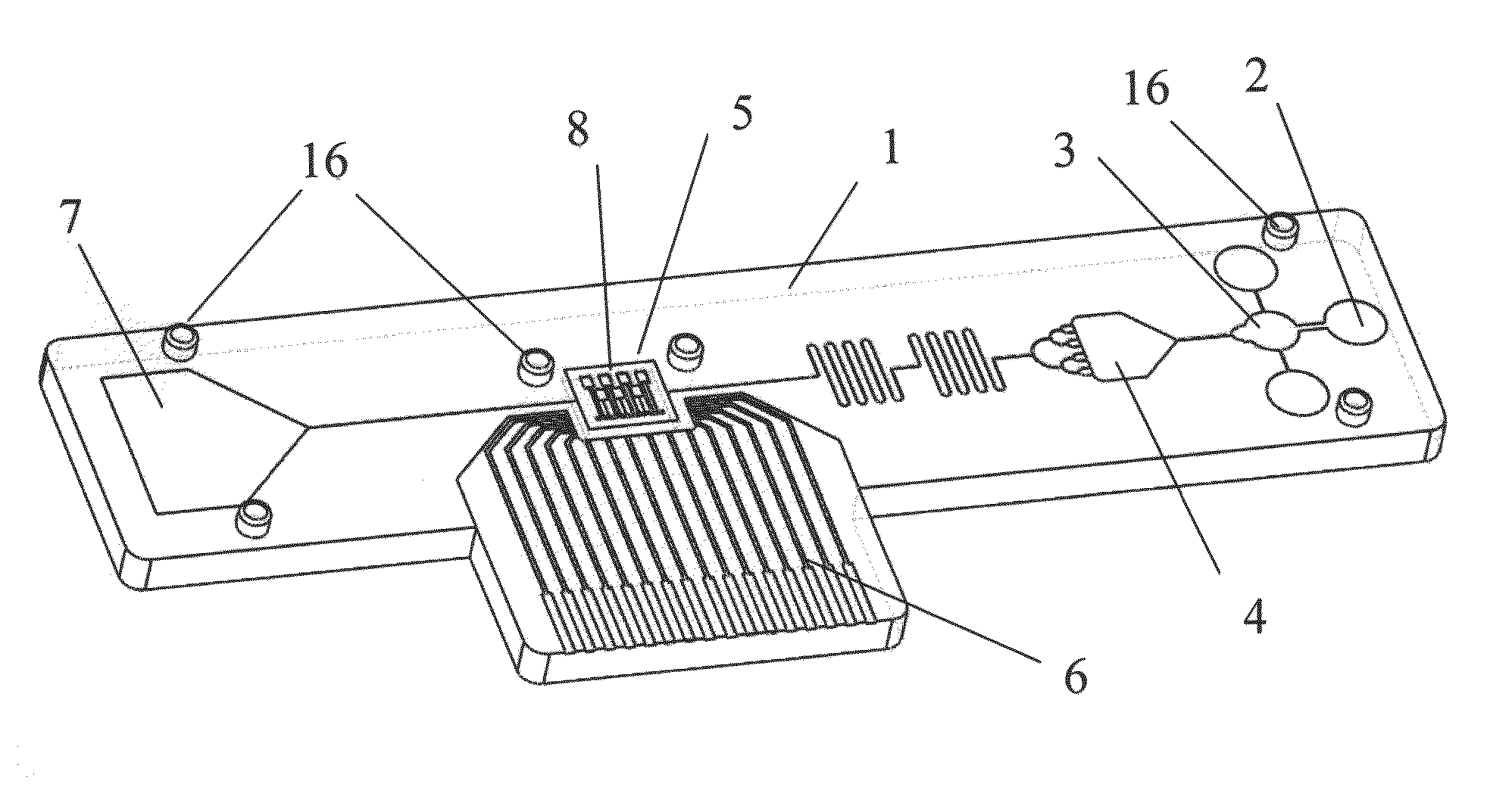
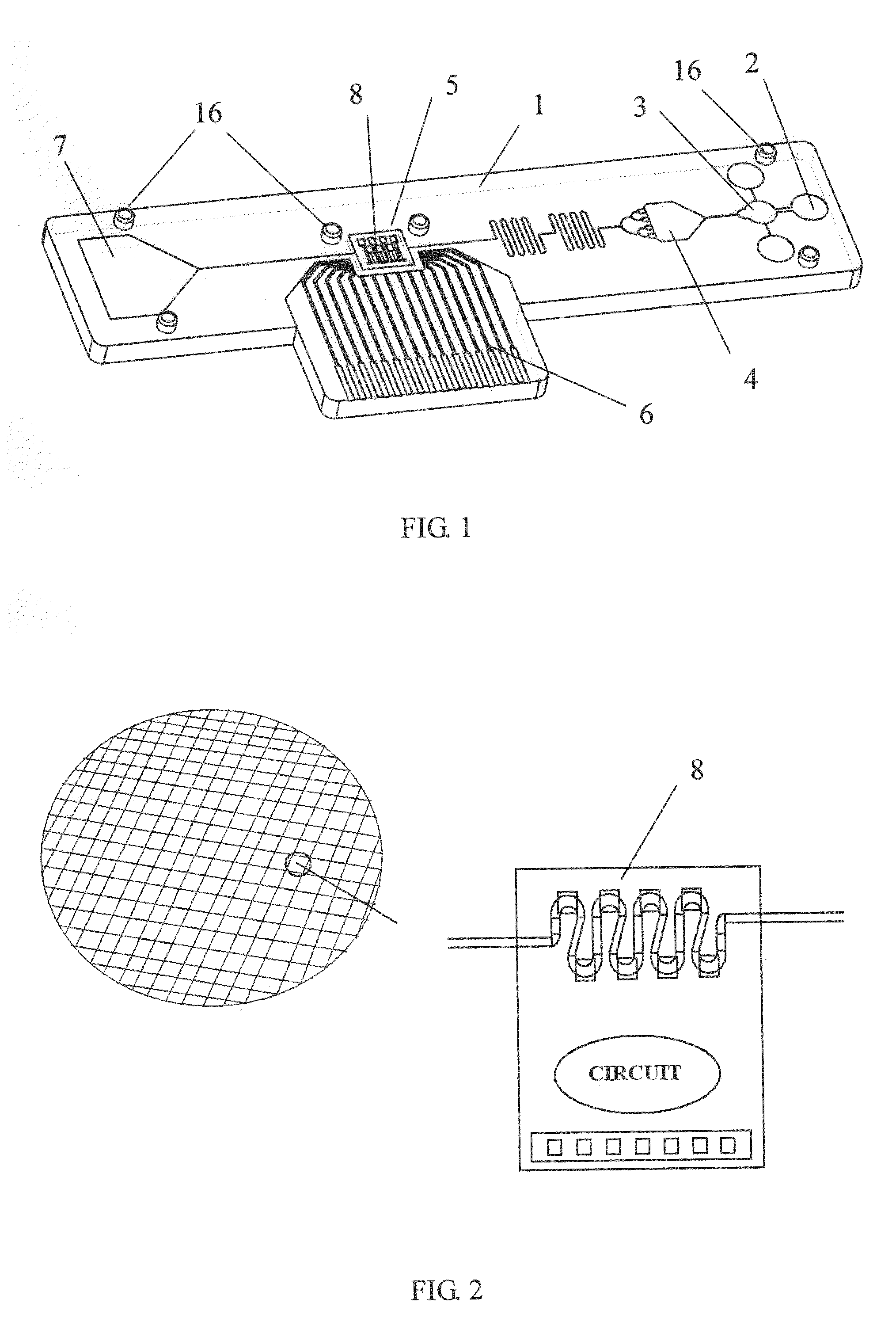
The present invention introduces a new type of biochip that uses an IC chip to detect and amplify signals, eliminating the need for fluorescence detection. The chip is embedded in a plastic substrate with microfluidic structures for sample handling. The chip detects particles like blood cells and biopolymers through micro- and nanofluidic channels. A capillary pump or suction area controls fluid flow and the chip converts the detected signals into electrical signals. The biochip can be easily mass-produced, is cheap, small, and can dispose of samples quickly. It is also suitable for disposable and small-volume use. The invention also suggests the use of an injection pump to further enhance sample flow.

Problems solved by technology

Its main limitation is a qualitative measurement; however, for many diagnoses quantitative measurement are often needed.
It is well known that the feature of the biochip is disposable, such as blood glucose test chip using electrochemical measurement; however, if the disease detection of the biochip is complex or need quantitative results, even microfluidic lab-on-chip devices, often need to employing fluorescence detection analysis.
Fluorescence analyzer is a standard equipment of the medical institution; it is an expensive and large equipment which is not portable.
Based on the above background, optical methods are often used in biological detection, for example, a fluorescent analyzer is needed to observe test results, but the fluorescence analyzer is a high cost instrument, it is difficult for the general public to have one in hand.

Method used


Image

  • Biochip and fabrication thereof
  • Biochip and fabrication thereof
  • Biochip and fabrication thereof

Examples


embodiment 1

[0033]FIG. 6 shows an embodiment of the IC chip with chip size of 4 * 4 (mm2), There is no amplifier or circuit in this IC chip, but main sensing structure composed of seven comb-shaped electrode elements, one of them as the control electrode of the circuit, while the remaining six comb electrode components were given different analytes-specific aptamers modified carbon nanotuhes. The target analytes may be six different cancer biomarkers in the serum or plasma. For wire bonding the pads with I / O ports of the plastic substrate 1, the entire pad layout is on the same side. With the subsequent plastic microfluidic channel packaging, a set of real-time sensing biochip may detect six kinds of different analytes.

embodiment 2

[0034]FIG. 7 shows another embodiment of the IC chip with chip size of 2.23884*2.28145 (mm2). Part A is a signal processing circuit connected to CNTFETs sensing element through a multiplexer to select different sensing element output. The signal processing circuit mainly comprises a clock generator, a chopper, and switched capacitor circuit. Part B is the sensing structure composing of nine comb-shaped electrode elements, one of them as the control electrode of the circuit, while the remaining eight comb-electrode components were given different analyte-specific aptamers modified carbon nanotubes. For wire bonding the pads with I / O ports of the plastic substrate 1, the entire pad layout is on the same side. With the subsequent plastic microfluidic channel packaging, a set of real-time sensing biochip may detect eight kinds of different analytes.

embodiment 3

[0035]FIG. 8 illustrates another embodiment of the IC chip with chip size of 2.364 * 1.794 (mm2). Part A shows the amplifier circuit capable of measuring nA to μA current changes, which mainly use the charge integrator for amplifying the input current signal into a voltage output. This area also contains three sets of operational amplifiers, switches, oscillators, and a multiplexer. The entire pads are on the same side, in order to facilitate follow-up integration with the plastic substrate 1. Part B is the counting structural elements, having a pore with the size of 30 microns, for counting the number of cancer cells in size of 15 to 25 microns. Since the height of the pore and micro fluidlc channel is around 30 microns, it needs an electroforming process to fabricate the thick metal seeding from the PAD layer of the IC chip.

[0036]In this embodiments the PDMS plate would not cover the outlet of microfluidic channel, but let micro fluid flow through the outlet and fully count all th...


PUM


Abstract

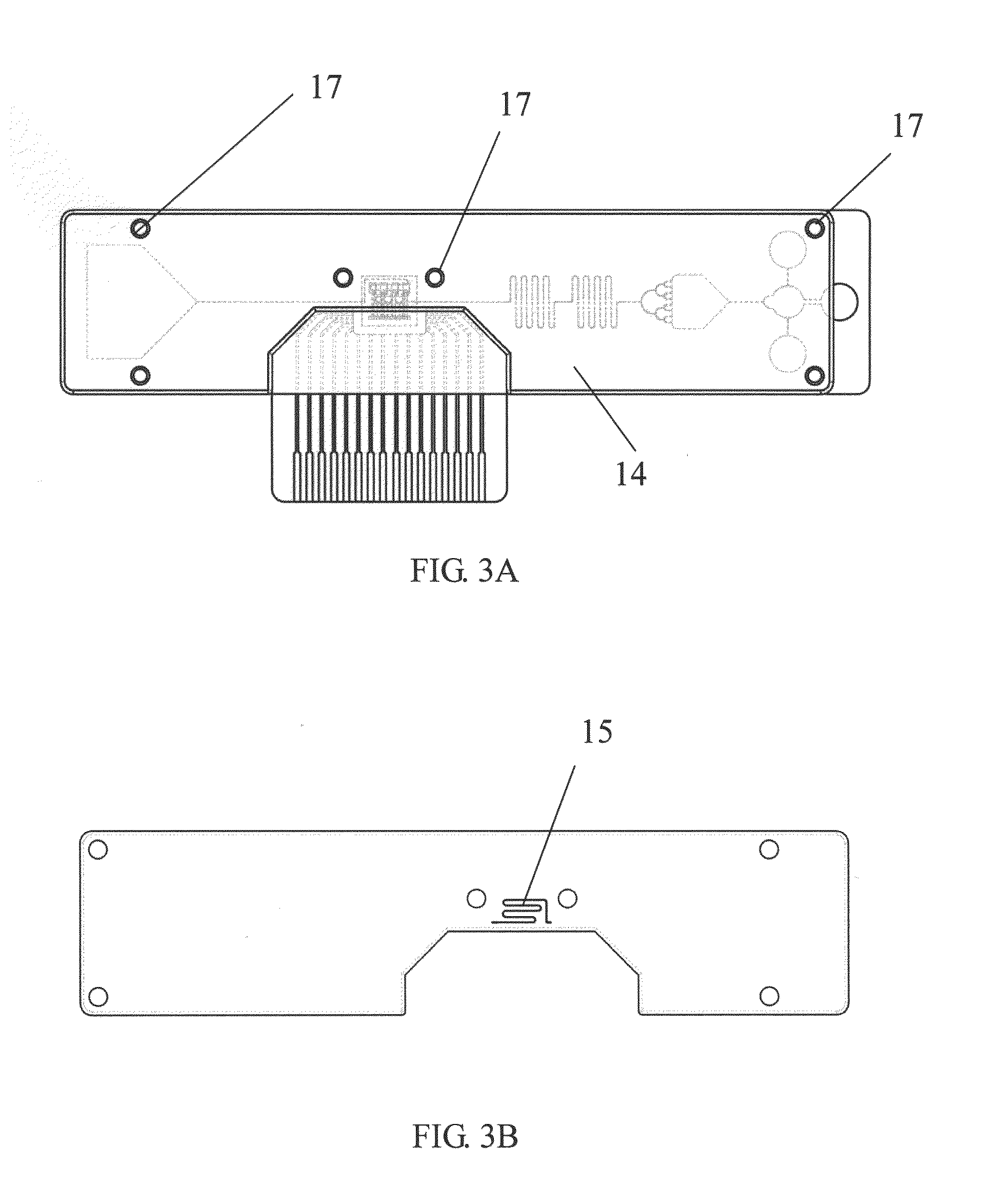
A biochip comprising a plastic substrate, an IC chip, and a sealing cover is disclosed in this invention. The plastic substrate combines the function of sample inlet area, separating structure, micro-fluidic channel, flow resistor, detection area, and capillary pump or suction area. Sealing the plastic substrate with porous cover could make the structure of micro-fluidic to form the capillary effect or degas-driven effect, and drive the sample naturally without extra pump. The detection area is constituted by the IC chip which is embedded into the plastic substrate, and the IC chip includes the amplifier circuit and detection structure. In the detection area, there uses the biological specific conjugates to catch the bio-particles, nano-particles, or macromolecule sensitively. And finally, transfer the detected electric signal to a mobile communication device.

Description

FIELD OF INVENTION[0001]The present invention is related to a biochip and its fabrication method. An IC chip embedded in the plastic substrate is formed by way of injection insert molding or hot embossing. The IC chip is for detecting nanoscale particles or biopolymer specimen electrically in the fluid sample with high specificity and sensitivity, The PDMS cover plate bonds with the plastic substrate through using vacuum packaging to form capillarity or degas status, which provide the driving force to drive the fluid flow in the microfluidic channel of the biochip.DESCRIPTION OF RELATED ART[0002]The point-of-care diagnosis means a direct measurement in the patient's side, which features a disposable, low cost, simple to use, and just a small amount of sample for leading to available test results. In addition to using point-of-care diagnosis for clinical testing by the professionals at the hospital the patients or the general public can also use the point-of-care diagnosis in any non...

Claims


Application Information

Patent Timeline
IPC IPC(8): G01N27/00H01L23/31
CPCG01N27/00H01L23/31B81C1/00015G01N27/128G01N33/487H01L2924/0002B01L3/502715B01L2300/0645B01L2300/0816B01L2400/0406H01L2924/00
Inventor HUANG, JUNG-TANG
Owner HUANG JUNG TANG
Learn More