
Thermally-assisted magnetic recording head having temperature sensor embedded on dielectric waveguide

a technology of dielectric waveguide and temperature sensor, which is applied in the field of thermally assisted magnetic recording head, can solve the problems of inability to avoid the heat generation of the near-field light generator due to the light penetrating into the inside, and the method is not suitable for practical use, so as to reduce performance degradation, reduce the size of the spot, and reduce the effect of heat generation

Active Publication Date: 2013-10-03
TDK CORPARATION
View PDF0 Cites 15 Cited by
  • Summary
  • Abstract
  • Description
  • Claims
  • Application Information

AI Technical Summary

Benefits of technology

The patent describes a configuration for a magnetic recording device. The device has a temperature sensor that can detect the heat generated by the near-field light generator, allowing for highly accurate temperature detection. The temperature sensor absorbs minimal light, reducing energy loss and efficiently heating the magnetic recording medium. This results in excellent thermal assisted magnetic recording. The configuration also helps to prevent performance degradation caused by excessive heating of the near-field light generator, achieving high light energy transmission efficiency and generating intense near-field light with a narrow spot size.

Problems solved by technology

However, because the metallic scatterer that is a near-field light generator deforms due to excessive heating, this method is not suited for practical use.
When the thermal expansion is significant, the thermal assisted magnetic recording head may approach too much and collide to the magnetic recording medium, thereby causing damages.
The heat generation of the near-field light generator due to the light penetrating into the inside is not avoidable even when surface plasmon is used.

Method used


Image

  • Thermally-assisted magnetic recording head having temperature sensor embedded on dielectric waveguide
  • Thermally-assisted magnetic recording head having temperature sensor embedded on dielectric waveguide
  • Thermally-assisted magnetic recording head having temperature sensor embedded on dielectric waveguide

Examples


Embodiment Construction

[0026]A thermal assisted magnetic recording head according to embodiments of the present invention is explained with reference to the drawings.

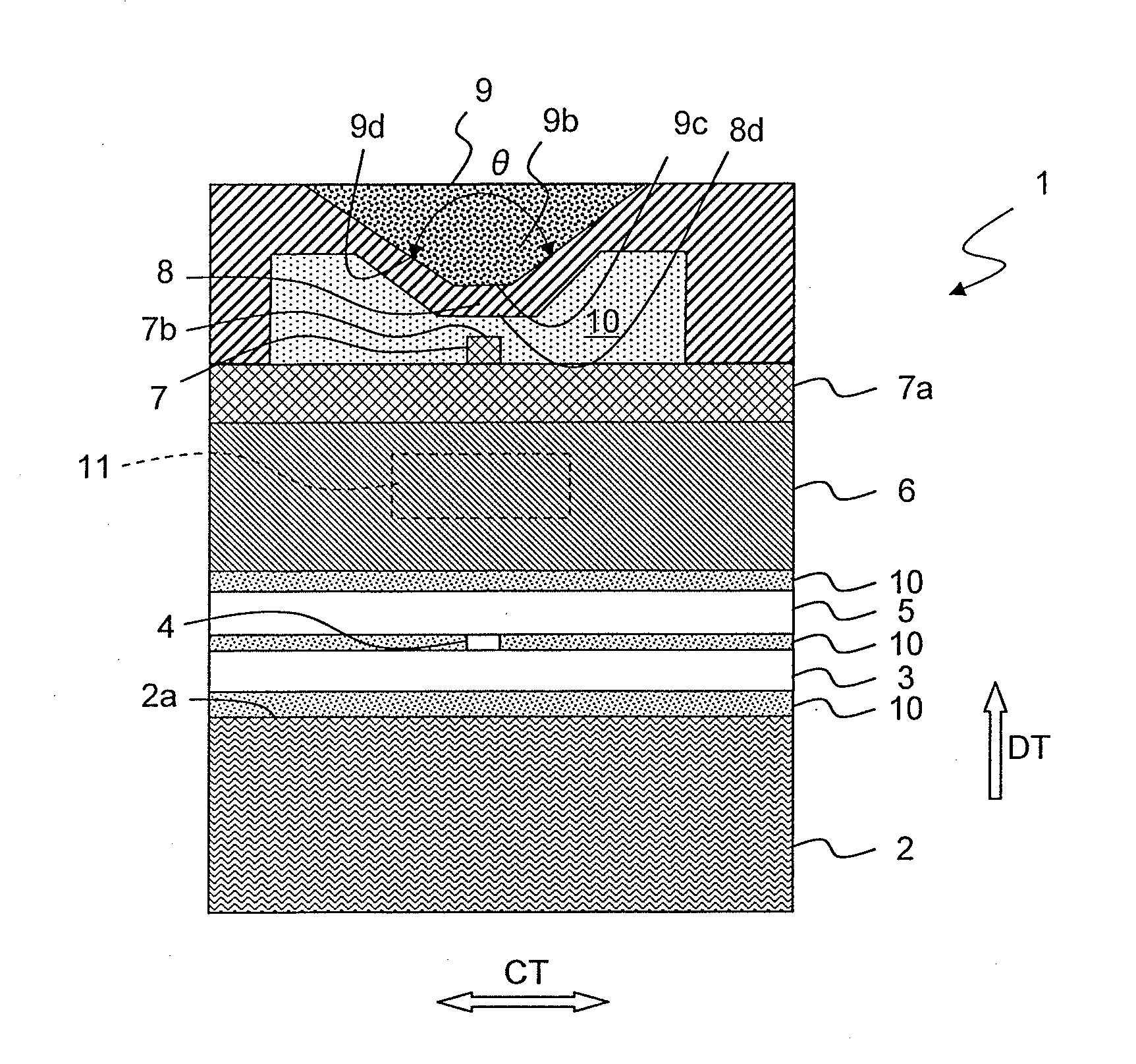
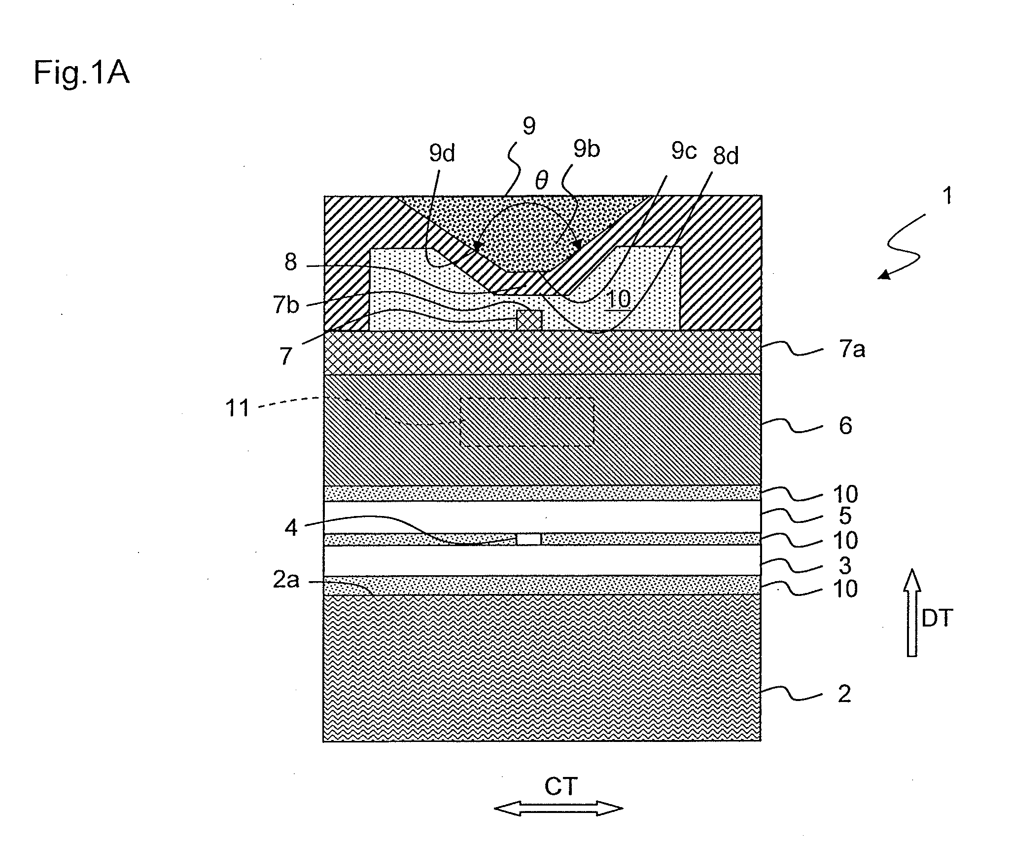
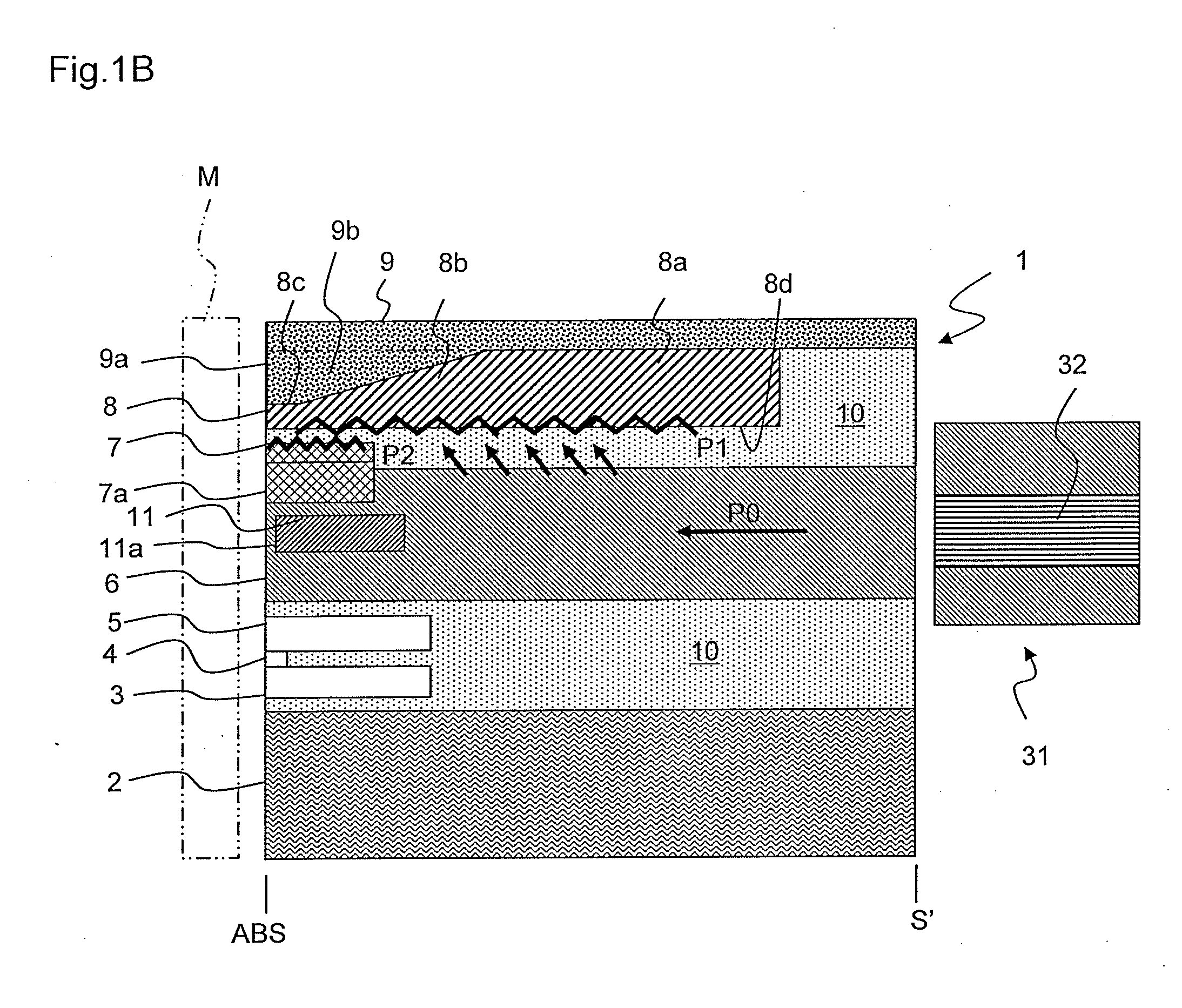
[0027]FIG. 1A is a main portion schematic view illustrating an air bearing surface (ABS) of a thermal assisted magnetic recording head according to an embodiment of the present invention. FIG. 1B is a main portion schematic view of the thermal assisted magnetic recording head, the schematic view illustrating a cross section orthogonal to the ABS and a principle plane of a substrate. The ABS is a surface of the thermal assisted magnetic recording head that faces a magnetic recording medium, and the principle plane of the substrate is a plane on which the thermal assisted magnetic recording head is formed.

[0028]A thermal assisted magnetic recording head 1 (hereinafter, occasionally referred to also as “magnetic head”) has a magneto resistance (MR) element 4 that is provided above a substrate 2 made of ALTIC (Al2O3—TiC). The MR element 4 has an ...


PUM

PropertyMeasurementUnit
distanceaaaaaaaaaa
wavelengthaaaaaaaaaa
recession distanceaaaaaaaaaa

Abstract

A thermal assisted magnetic recording head includes a dielectric waveguide that is configured to propagate propagation light a metal waveguide that is provided facing the dielectric waveguide and that couples to the propagation light propagating through the dielectric waveguide in a surface plasmon mode, thereby generating and propagating surface plasmon, a near-field light generator that is exposed on an air bearing surface facing a magnetic recording medium either at an end part of the metal waveguide or at a position facing the end part of the metal waveguide, and that generates near-field light from the surface plasmon, a magnetic pole for magnetic recording that is exposed on the air bearing surface, and a temperature sensor that is arranged inside the dielectric waveguide.

Description

BACKGROUND OF THE INVENTION[0001]1. Field of the Invention[0002]The present invention relates to a thermal assisted magnetic recording head that is provided with a temperature sensor.[0003]2. Description of the Related Art[0004]In order to increase the recording density of magnetic recording, a recording system has been known that allows to record stably to particles with a small diameter by increasing a magnetic anisotropy constant of a magnetic recording medium and at the same time allows to record easily by heating a region to be recorded locally so as to decrease coercive force of the magnetic recording medium. A magnetic head that performs recording using the above-described recording system is referred to as a thermal assisted magnetic recording head. Near-field light is preferably used to heat when a region on the magnetic recording medium that is to be heated is smaller than a wavelength of light.[0005]U.S. Pat. No. 7,330,404 discloses a technology that matches an oscillatio...

Claims


Application Information

Patent Timeline
Patent Type & Authority Applications(United States)
IPC IPC(8): G11B13/04G11B19/20G11B21/24
CPCG11B5/314G11B2005/0021G11B5/607
Inventor KOMURA, EIJISHIMAZAWA, KOJICHOU, TSUTOMUHARA, SHINJITANAKA, KOSUKEHOSOI, RYO
Owner TDK CORPARATION
Learn More