Circuitry for and a method of compensating drift in resistance in eddy current probes

a technology of eddy current probes and circuits, applied in the field of non-destructive testing, can solve the problems of unaccounted for calibration procedures, difficulty in eliminating the effect of ec probe conductor resistance, and inconvenient measurement of conductor resistance, so as to improve the accuracy of eddy current measurement, accurate and dynamic measurement of circuit resistance and the amount of ec probes

Inactive Publication Date: 2013-10-03
OLYMPUS SCI SOLUTIONS AMERICAS
View PDF10 Cites 2 Cited by
  • Summary
  • Abstract
  • Description
  • Claims
  • Application Information

AI Technical Summary

Benefits of technology

[0012]The invention disclosed herein enables the accurate and dynamic measurement of EC probe circuit resistance and the amount of energy lost in the EC coils, and therefore allows the improved accuracy in eddy current measurement whereas existing practice lacks an efficient approach to measure the dynamically changing EC probe circuit resistance.
[0015]Accordingly, it is a general objective of the present disclosure to enable the EC instrument to produce more accurate measurement results based on dynamic coil resistance in accordance with the specific operational conditions.

Problems solved by technology

The conductor has electric resistance, and this conductor resistance becomes an unwanted part of the measurement.
However, the task of eliminating the effect of EC probe conductor resistance becomes challenging because the resistance is a function of temperature.
As the operational temperature changes, the probe conductor resistance changes, introducing changes in measurement results unknown to operator and therefore un-accounted for during the calibration procedures.
As a result, the EC measurement that the instrument performs becomes less accurate.
The test sample in which the eddy current flows is not a perfect electrical conductor and therefore responsible for a portion of the energy loss in this process.
However, the need for the extra reference coil in this patent increases the size and the cost of the probe and limits the range of the inspection that the probe can access to.
The primary detector in this differential EC transducer incorporates two similar search coils and an additional coil, which presents a similar drawback as seen in U.S. Pat. No. 4,893,079.

Method used


Image

  • Circuitry for and a method of compensating drift in resistance in eddy current probes
  • Circuitry for and a method of compensating drift in resistance in eddy current probes
  • Circuitry for and a method of compensating drift in resistance in eddy current probes

Examples


Embodiment Construction

[0023]The table below provides reference to the symbols used in the present disclosure.

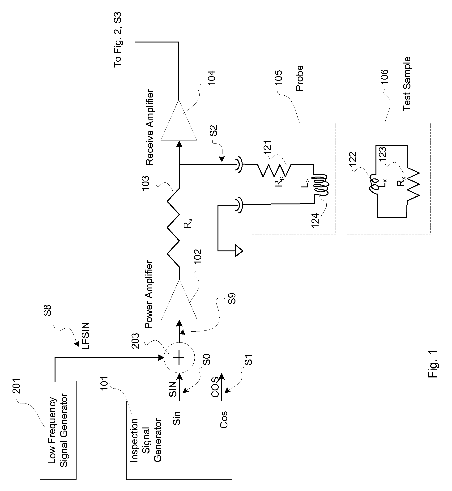
VariableDefinitionRpProbe Conductor ResistanceLpProbe InductanceRxTest Sample ResistanceLxTest Sample InductanceRsresistance of Resistor 103Rtotal resistance of the probe circuitLtotal inductance of the probe circuitfHinspection frequency (frequency of the signals generated bythe Inspection Signal Generator 101)fLlow frequency (frequency of the signals generated by theLow Frequency Signal Generator 201)

[0024]Referring to FIG. 1, the “acquisition” or “receiving” part of the circuitry of an EC instrument according to the preferred embodiment comprises a Low Frequency Signal Generator 201, an Inspection Signal Generator 101, an Adder 203, a Power Amplifier 102, a Resistor 103 (Rs), a Receiver Amplifier 104, a Probe 105, and a Test Sample 106.

[0025]Test Sample 106 is placed under Probe 105 for eddy current inspection or testing. Inside Probe 105, 121 represents Probe Conductor Resistance (Rp) and 124 ...


PUM


Abstract

Disclosed is an eddy current non-destructive inspection device which includes an eddy current probe with a probe conductor resistance dynamically changing due to operation conditions, such as temperature. The device further includes a signal generating circuit generating an inspection frequency signal and a low frequency signal. Sensed inspection frequency signals are processed to produce resulting signals with possible drift. A low frequency processing circuit includes a resistance calculator producing a substantially true value of the dynamic probe resistance, based on which compensation operations are configured to correct the drifted resulting signals and produce corrected resulting signals.

Description

FIELD OF THE INVENTION[0001]The present invention relates to non-destructive testing (NDT) and more particularly to an eddy current array (ECA) probe or an eddy current (EC) probe.BACKGROUND OF THE INVENTION[0002]An EC probe is normally manufactured using an electric conductor and winding it into a coil. The conductor has electric resistance, and this conductor resistance becomes an unwanted part of the measurement. This is because part of the conductor resistance can be often confused with the EC measurements being made. A typical instrument needs to be calibrated by the user at the start of operation to remove as much as possible the effects of the probe conductor resistance. However, the task of eliminating the effect of EC probe conductor resistance becomes challenging because the resistance is a function of temperature. As the operational temperature changes, the probe conductor resistance changes, introducing changes in measurement results unknown to operator and therefore un-...

Claims


Application Information

Patent Timeline
Patent Type & Authority Applications(United States)
IPC IPC(8): G01R35/00
CPCG01N27/9046
Inventor THOMAS, ANDREW
Owner OLYMPUS SCI SOLUTIONS AMERICAS
Why Eureka
Try Eureka