Eureka AIR delivers breakthrough ideas for toughest innovation challenges, trusted by R&D personnel around the world.

System and method for reducing trapped energetic proton or energetic electron flux at low earth orbits

a technology of energetic proton and electron flux, which is applied in the field of radiation protection, can solve the problems of system failure, inability to function, and essentially impractical hardening against such high-energy protons, and achieve the effects of reducing energy electron flux enhancement, reducing energetic proton flux, and reducing energy proton flux trapped in the inner radiation bel

Inactive Publication Date: 2013-07-18
BAE SYST INFORMATION & ELECTRONICS SYST INTERGRATION INC
View PDF3 Cites 2 Cited by
  • Summary
  • Abstract
  • Description
  • Claims
  • Application Information

AI Technical Summary

Benefits of technology

The present invention provides a system and method for reducing pesky particles and enhanced electron flux in the inner radiation belt and gap caused by solar storms or natural nuclear explosions. The invention also allows for the use of commercial electronics with submicron feature size on low-earth-orbit satellites and microsatellites without the constraints of energetic proton fluxes trapped at the inner radiation belts. The invention further ensures the efficient reduction of trapped proton fluxes and the use of ultra low frequency electromagnetic waves. The invention thus solves the problem of space-based electronic circuit anomalies and increases the useful lifetime of low-earth-orbit satellites.

Problems solved by technology

Radiation effects in spacecraft electronics caused by the inner radiation belt protons are the major cause of performance anomalies and lifetime of Low Earth Orbit satellites.
Such systems cannot function in the presence of the trapped 30 to 100 MeV protons, as hardening against such high-energy protons is essentially impractical.
The interaction of energetic protons with electronic devices of modern spacecraft results in high rates of anomalies due to Single Event Effects (SEE).
Such anomalies range from nuisance effects that require operator intervention to debilitating effects leading to functional or total loss of the spacecraft.
A set of operational problems occur when protons deposit enough charge in a small volume of silicon to change the state of memory cell, so that a one becomes zero and vice versa.
The memories can become corrupted and lead to erroneous commands.
Such soft errors are referred to as Single Event Upsets (SEU) and often generate high background counts to render the sensor unusable.
Some devices can be triggered into a high current drain, leading to burn-out and hardware failure, known as single event latch-up or burn-out.
Other devices suffer dielectric breakdown and rupture.
At present, satellites with micron size Commercial-Off-The Shelf (COTS) electronics experience serious effects mainly when transiting the SM.
However, it is very hard to shield against proton fluxes with energy in excess of 20 to 30 MeV.
This could preclude their use even for orbit latitudes different than the SAA.
Further hardening the microelectronic components, besides the added weight, is very ineffective for proton energies higher than 20 to 30 MeV.
The recent tests have shown that the SEU cross section for energies between 1 to 10 MeV for bulk 65 nm Complementary Metal Oxide Semiconductor (CMOS) technology is by two orders of magnitude higher than for micron size devices, rendering current shielding level inadequate even at low proton energies.
Furthermore open standards drive down development and life-time support costs reduce the time to market for new products.
The SEE issue for submicron CMOS or other electronic components presents a major dilemma, since it will prohibit use of COTS circuits with sub-micron size features and will limit the use of micro-satellites at LEO orbits.
Thus it is difficult to shield against 30 to 100 Mev protons to the level required by sub-micron features of current and future commercial electronic components.

Method used


Image

  • System and method for reducing trapped energetic proton or energetic electron flux at low earth orbits
  • System and method for reducing trapped energetic proton or energetic electron flux at low earth orbits
  • System and method for reducing trapped energetic proton or energetic electron flux at low earth orbits

Examples


Embodiment Construction

[0040]The particular values and configurations discussed in these non-limiting examples can be varied and are cited merely to illustrate at least one embodiment and are not intended to limit the scope thereof.

1. The Structure of the Radiation Belts

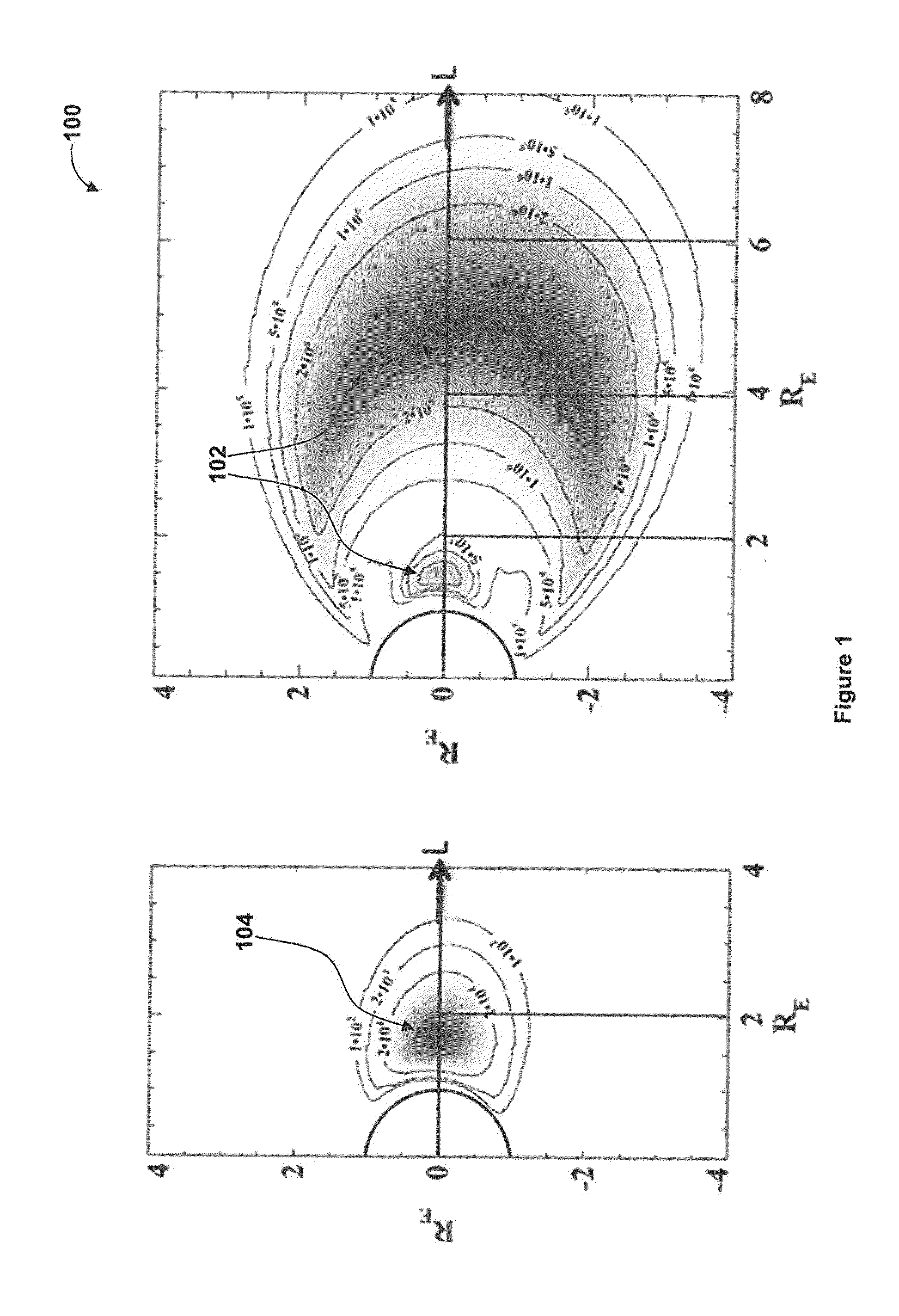
[0041]Radiation Belts (RB), also known as Van-Allen belts, are the locus of energetic electron and protons trapped by the Earth's magnetic field. It is customary and convenient to describe a given magnetic field line by its L value. The L value corresponds to the radial location of its intersection with the magnetic equator in units of Earth radius (RE). FIG. 1 illustrates a schematic, diagram of the proton and electron RB structure as a function of L shell. The intensity of a proton radiation belt 104 is confined inside the L=2 value. Contrary to this, the electron radiation belts 102 have two peaks one inside L=2 and another between L=4 and L=5, separated by a gap between L=2 and L=3. It is customary to label regions with L3 as the outer...


PUM


Abstract

A system and method for improving the survivability of space systems following a High Altitude Nuclear Explosion (HANE) incident resulting in energetic electrons being trapped in the inner radiation belt of Earth is disclosed. The ULF electromagnetic waves is generated by space or ground based transmitters and the frequency range is selected such that the injected waves are in gyrofrequency resonance with trapped energetic particles. The Radiation Belt Remediation (RBR) depends on the wave-number of the injected waves and the wave-number of the injected waves increases along their propagation path when they approach the cyclotron frequency of the dominant or minority ions 0+, He+ and H+.

Description

CROSS-REFERENCE TO RELATED APPLICATIONS[0001]This Application is a Continuation-in-Part of U.S. Application Ser. No. 61 / 448,480 filed Mar. 2, 2011; and this application claims rights under 35 U.S.C. §119(e) from U.S. application Ser. No. 13 / 409,340 filed Mar. 1, 2012, the contents of both of which are incorporated herein by reference.TECHNICAL FIELD[0002]Embodiments are generally related to radiation protection. Embodiments also relate to protecting an electronic component against space environment radiations. Embodiments additionally relate to a system and method for reducing energetic proton flux, trapped in the inner radiation belt by injecting Ultra Low Frequency (ULF) electromagnetic waves. Embodiments additionally relate to a system and method for reducing energetic electron flux enhancements in the gap and inner belt caused by natural solar storms or High Altitude Nuclear Explosions (HANE).BACKGROUND OF THE INVENTION[0003]The structure and behavior of the energetic electrons ...

Claims


Application Information

Patent Timeline
IPC IPC(8): B01J19/12
CPCG21K1/00B01J19/12H01Q1/288
Inventor PAPADOPOULOS, KONSTANTINOS
Owner BAE SYST INFORMATION & ELECTRONICS SYST INTERGRATION INC
Why Eureka
Eureka Blog
Learn More