
Substrate cleaning method, substrate cleaning apparatus and storage medium for cleaning substrate

a cleaning method and substrate technology, applied in the direction of lighting and heating apparatus, chemistry apparatus and processes, cleaning using liquids, etc., can solve the problems of pattern damage, non-uniform distribution of cleaning liquid between circuit patterns, etc., and achieve the effect of avoiding circuit pattern damag

Active Publication Date: 2013-07-11
TOKYO ELECTRON LTD
View PDF4 Cites 36 Cited by
  • Summary
  • Abstract
  • Description
  • Claims
  • Application Information

AI Technical Summary

Benefits of technology

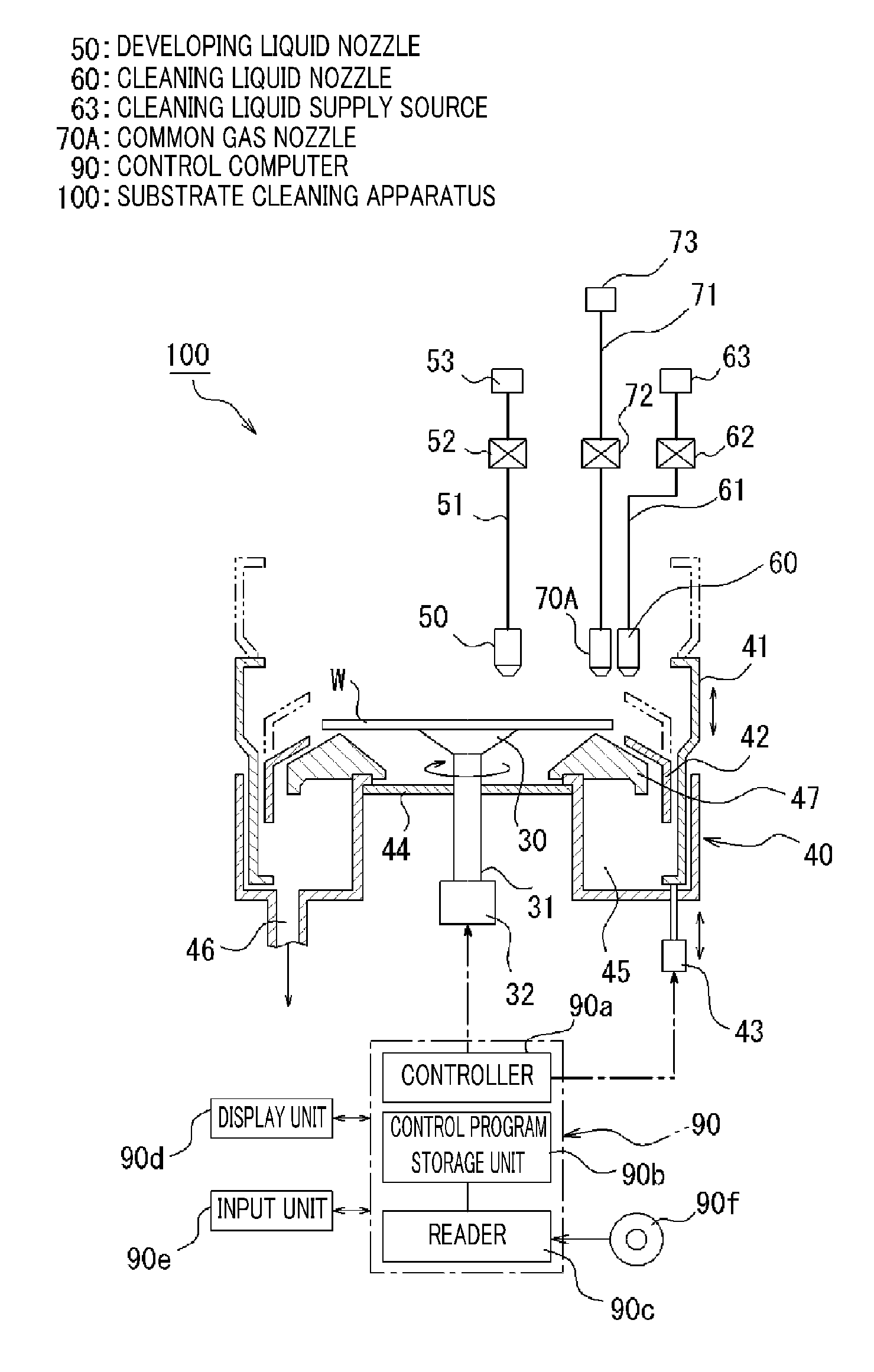
The patent text describes a method and apparatus for cleaning semiconductor substrates after they have been developed with minute circuit patterns. The invention aims to prevent damage to the circuit patterns and avoid the stream of cleaning liquid cutting into the substrate during the cleaning process. This is achieved by controlling the linear velocity of the cleaning liquid at the supply position of the substrate, reducing the rotation speed of the substrate, and controlling the centrifugal force and rotation time of the substrate to prevent pattern damage. The cleaning liquid is supplied towards the peripheral portion of the substrate from the central portion, while gas is discharged from the peripheral portion. This results in a liquid film being formed on the substrate surface and a drying region being formed with the residual liquid being removed in a diametrical direction of the substrate. Overall, this method and apparatus effectively prevent damage to the minute circuit patterns on semiconductor substrates during cleaning processes.

Problems solved by technology

As a result, distribution of the cleaning liquid remaining between the circuit patterns may become extremely non-uniform, and, accordingly, the pattern may be damaged by a stress generated between the circuit patterns.

Method used


Image

  • Substrate cleaning method, substrate cleaning apparatus and storage medium for cleaning substrate
  • Substrate cleaning method, substrate cleaning apparatus and storage medium for cleaning substrate
  • Substrate cleaning method, substrate cleaning apparatus and storage medium for cleaning substrate

Examples


Embodiment Construction

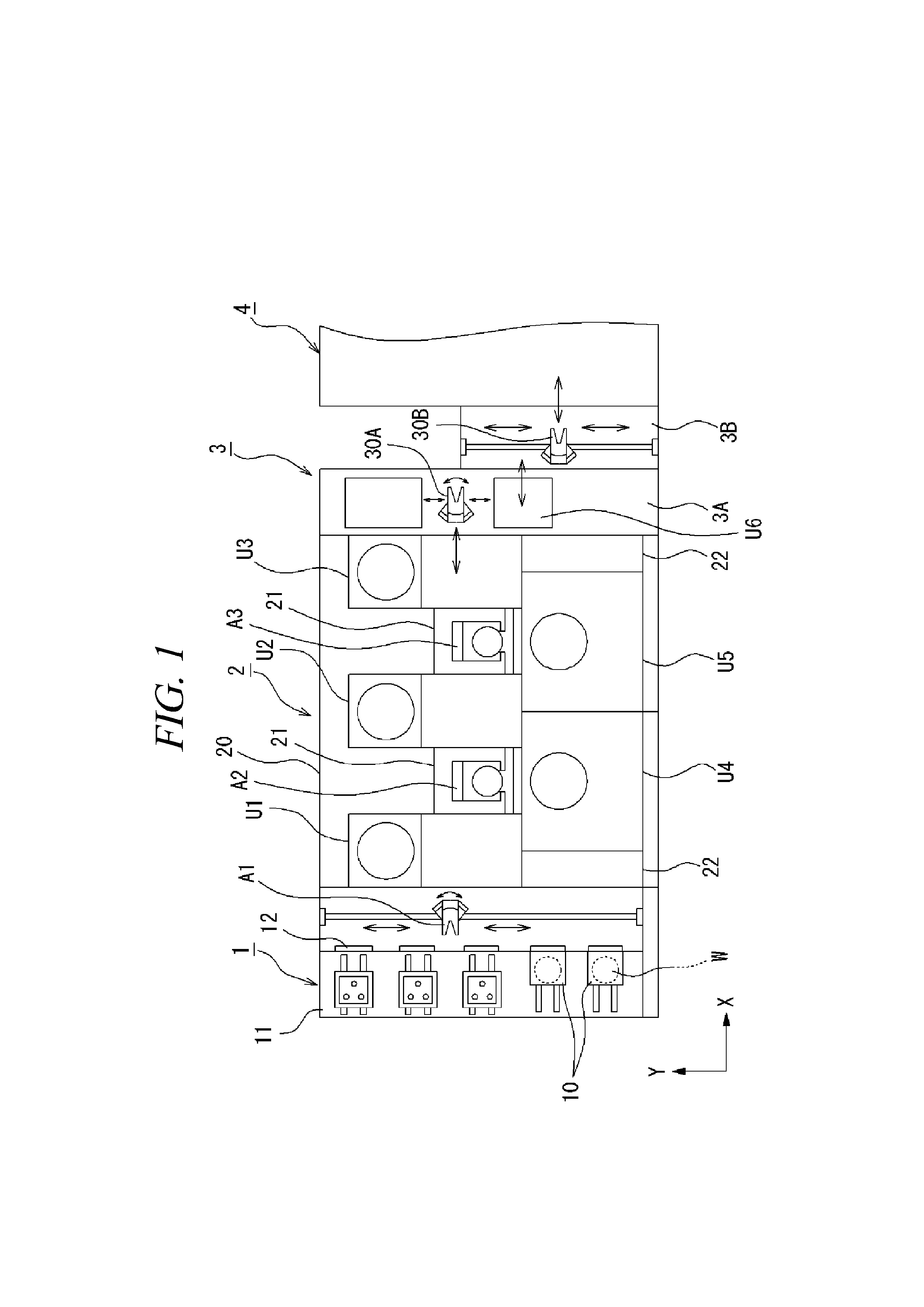
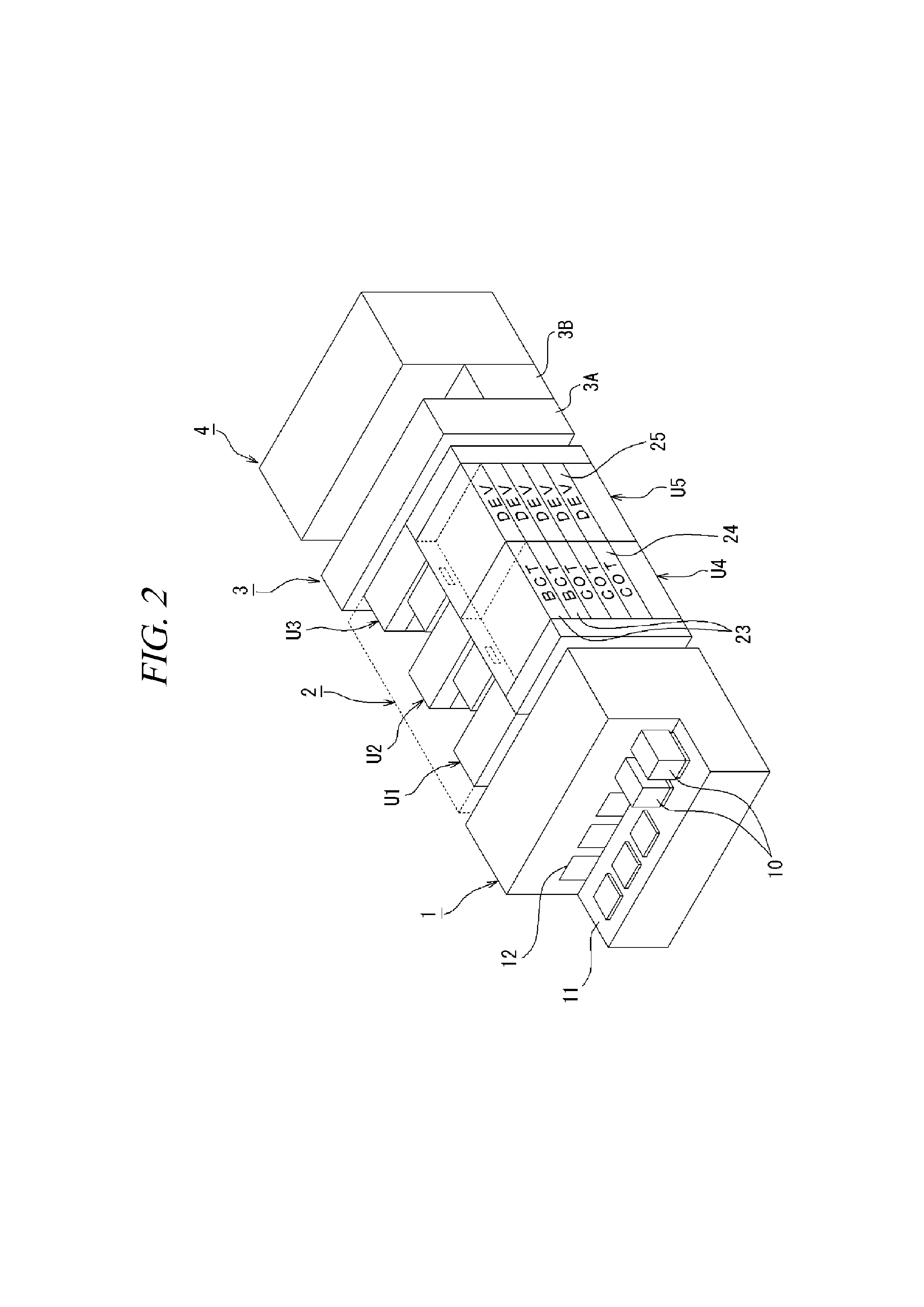
[0056]Hereinafter, illustrative embodiments will be described with reference to the accompanying drawings. Here, a substrate cleaning apparatus in accordance with the illustrative embodiments is described to be applied to a processing system in which an exposure apparatus is coupled to a coating and developing apparatus.

[0057]The processing system includes a carrier station 1, a processing block 2, an exposure block 4 and an interface block 3. The carrier station 1 is configured to load and unload carriers 10 each of which accommodates therein a multiple number of, e.g., about 25 sheets of wafers W as processing target substrates while being sealed. The processing block 2 is configured to perform a resist coating process, a developing process and so forth on a wafer W taken out of the carrier station 1. The exposure block 4 is configured to perform liquid immersion lithography on a surface of the wafer W after a liquid layer transmitting light is formed on the surface of the wafer W...


PUM


Abstract

A substrate cleaning method is capable of preventing a liquid stream on a substrate from being cut and circuit patterns thereon from being damaged. The substrate cleaning method includes a liquid film forming process that forms a liquid film on an entire substrate surface by supplying a cleaning liquid L from a central portion of the substrate W toward a peripheral portion thereof while rotating the substrate; a drying region forming process that discharges a gas G on the substrate surface and removes the cleaning liquid on the substrate surface; and a residual liquid removing process that removes the cleaning liquid remaining between the circuit patterns by discharging a gas G while moving in a diametrical direction of the substrate.

Description

CROSS-REFERENCE TO RELATED APPLICATION[0001]This application claims the benefit of Japanese Patent Application No. 2012-000562 filed on Jan. 5, 2012, the entire disclosures of which are incorporated herein by reference.FIELD OF THE INVENTION[0002]The present disclosure relates to a substrate cleaning method and a substrate cleaning apparatus for cleaning a substrate by supplying a cleaning liquid onto the substrate having thereon a circuit pattern, and also relates to a storage medium for cleaning the substrate.BACKGROUND OF THE INVENTION[0003]In a semiconductor manufacturing process, a circuit pattern is formed through a series of processes of coating a photoresist film on a substrate such as a semiconductor wafer, exposing the photoresist film to light with a preset circuit pattern and developing the photoresist film. This process is called a photolithography process. In the photolithography process, a processing system in which an exposure apparatus is connected to a coating and ...

Claims


Application Information

Patent Timeline
IPC IPC(8): H05K3/26
CPCH05K2203/1509H05K3/26H01L21/302B08B3/024B08B5/02H01L21/67028H01L21/67034
Inventor YOSHIHARA, KOUSUKETANAKA, KEIICHIICHINOMIYA, HIROSHI
Owner TOKYO ELECTRON LTD
Learn More