
Fluid leak detection system

a leak detection system and flue gas technology, applied in the direction of measuring devices, instruments, structural/machine measurement, etc., can solve the problems of time-consuming and costly replacement of the casing or the leakage may occur in the cooling water circuit, and the casing of the gas turbine or components located within the casing may need replacement,

Inactive Publication Date: 2013-07-11
GENERAL ELECTRIC CO
View PDF2 Cites 28 Cited by
  • Summary
  • Abstract
  • Description
  • Claims
  • Application Information

AI Technical Summary

Benefits of technology

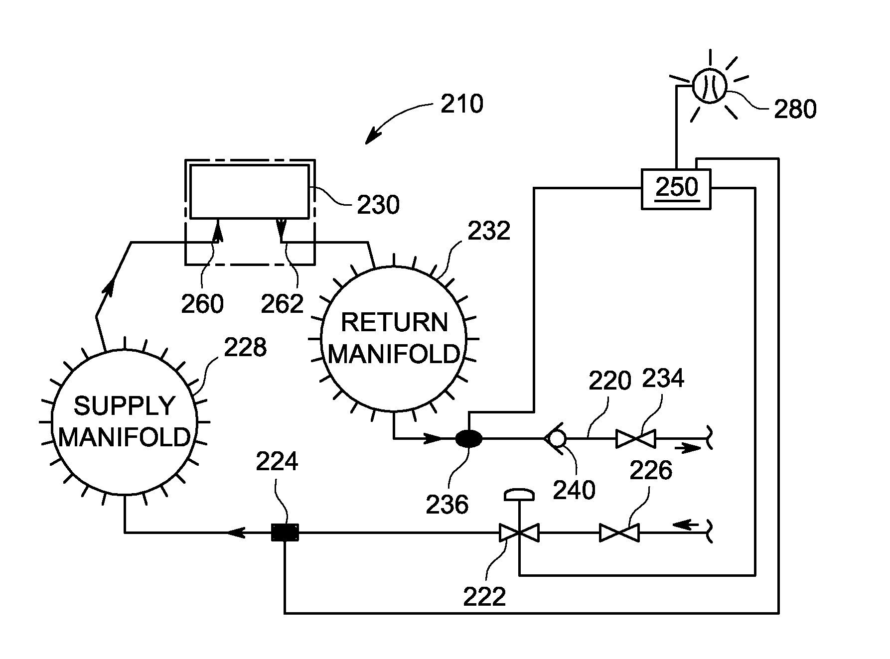
The invention provides a fluid leak detection system for a fluid-cooled device, which includes an inlet flow meter, an outlet flow meter, and a controller. The inlet flow meter monitors the inlet of the device for temperature and flow rate, while the outlet flow meter monitors the outlet of the device for temperature and flow rate. The controller analyzes the measured temperatures and flow rates, compensates for temperature effects, and calculates the actual flow rate difference between the inlet and outlet flows. This difference indicates a leak condition in the device. The system also includes a shutoff valve that can prevent fluid flow through the conduit. The technical effect of the invention is to provide a reliable and efficient way for detecting fluid leaks in fluid-cooled devices.

Problems solved by technology

However, a leak may occur in the cooling water circuit.
Leakage of the cooling water may cause the casing of the gas turbine or components located within the casing to need replacement.
Replacement of the casing or the components located within the casing may become time-consuming and costly.
However, a leak may also occur in the cooling water circuit of the liquid fuel purge system, which may also cause the water cooled valve to operate incorrectly.
The leak may also cause casing or other gas turbine component issues.

Method used


Image

  • Fluid leak detection system
  • Fluid leak detection system
  • Fluid leak detection system

Examples


Embodiment Construction

[0013]As used herein the terms module and sub-module refer to an application specific integrated circuit (ASIC), an electronic circuit, a processor (shared, dedicated, or group) and memory that executes one or more software or firmware programs, a combinational logic circuit, and / or other suitable components that provide the described functionality. For example, controllers or control modules may include one or more such modules.

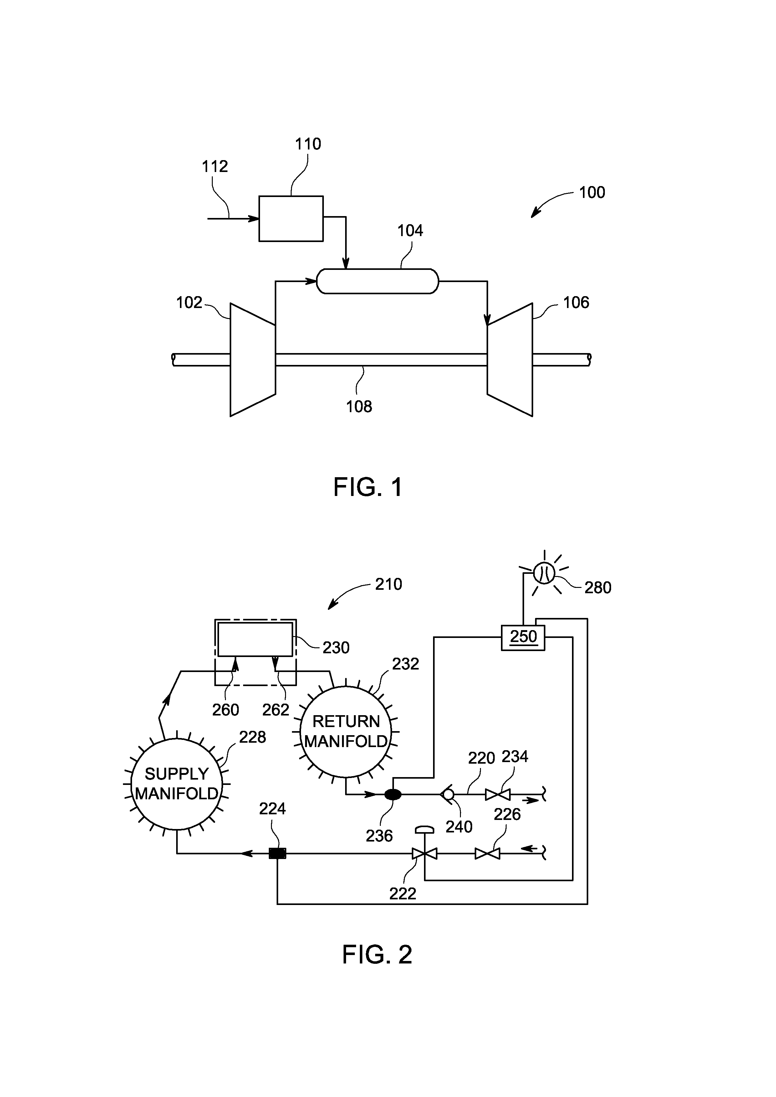
[0014]FIG. 1 is a schematic diagram of an embodiment of a gas turbine system 100. The system 100 includes a compressor 102, a combustor 104, a turbine 106, a shaft 108 and a fuel nozzle 110. In an embodiment, the system 100 may include a plurality of compressors 102, combustors 104, turbines 106, shafts 108 and fuel nozzles 110. As depicted, the compressor 102 and turbine 106 are coupled by the shaft 108. The shaft 108 may be a single shaft or a plurality of shaft segments coupled together to form shaft 108.

[0015]In an aspect, the combustor 104 uses liquid a...


PUM


Abstract

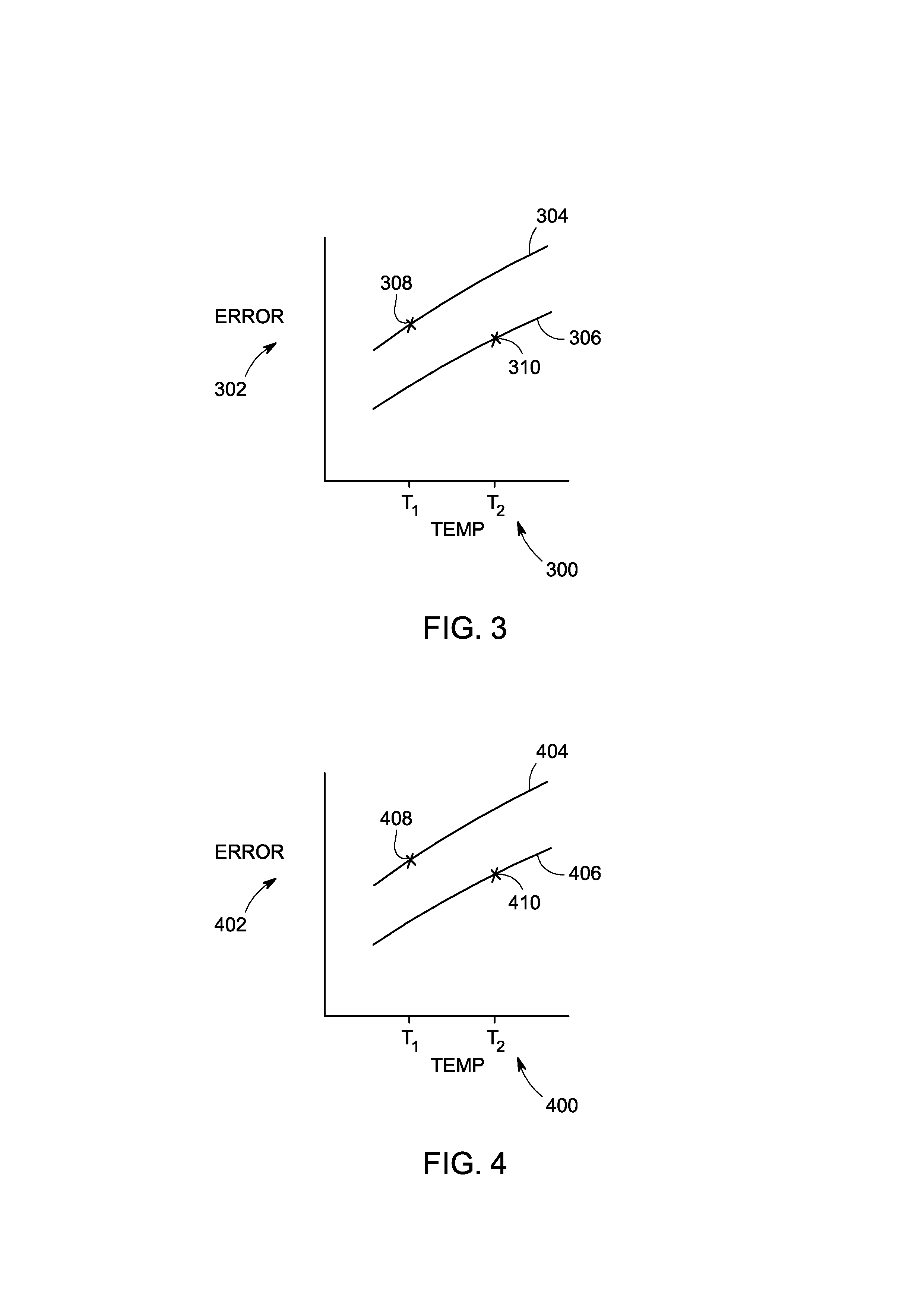
A fluid leak detection system is provided, and includes a fluid conduit, a fluid-cooled device having an inlet and an outlet, an inlet flow meter, an outlet flow meter, and a controller. The inlet flow meter and inlet flow meters are fluidly connected to the fluid conduit. The inlet flow meter monitors the inlet of the fluid-cooled device for an inlet temperature and an inlet flow rate. The inlet and outlet flow meters each have flow meter drift versus process fluid temperature curves as well as drift versus ambient temperature curves, wherein the curves for the inlet flow meter differ from the outlet flow meter. The outlet flow meter monitors the outlet of the fluid-cooled device for an outlet temperature and an outlet flow rate. The controller is in communication with the inlet flow meter and the outlet flow meter.

Description

BACKGROUND OF THE INVENTION[0001]The subject matter disclosed herein relates to a fluid leak detection system, and more specifically to a fluid leak detection system having a controller with control logic for monitoring the fluid leak detection system and determining if a leak condition exists.[0002]Traditionally, gas turbine flame detectors have been used to ensure the presence of a flame during gas turbine light-off and operation. Some flame detectors employ a cooling coil that uses water (which may contain a mixture of various anti-freeze constituents) as a cooling medium to keep a flame detector sensor below a threshold temperature. However, a leak may occur in the cooling water circuit. Leakage of the cooling water may cause the casing of the gas turbine or components located within the casing to need replacement. Replacement of the casing or the components located within the casing may become time-consuming and costly.[0003]Cooling water may also be employed to cool a liquid f...

Claims


Application Information

Patent Timeline
Patent Type & Authority Applications(United States)
IPC IPC(8): G01M3/28
CPCG01M3/3254G01M3/3227
Inventor HAINS, JOHN VICTORGU, YILISINGH, HARPALVANDEVELDE, JOHN PATRICKWHITRIGHT, BRIAN JAMES
Owner GENERAL ELECTRIC CO
Learn More