
Rebuildable Roller and Roller Bearing Assembly for a Belt Line Conveyor System and a Method of Use Thereof

a belt line conveyor and roller bearing technology, which is applied in bearing repair/replacement, manufacturing tools, rigid support of bearings, etc., can solve the problems of significantly increasing the cost of operating and maintaining conveyors, and significantly increasing the cost of tubular roller shafts. the cost of bearings located at terminal ends

Inactive Publication Date: 2013-06-06
KAMINSKI JR MICHAEL RICHARD
View PDF16 Cites 8 Cited by
  • Summary
  • Abstract
  • Description
  • Claims
  • Application Information

AI Technical Summary

Benefits of technology

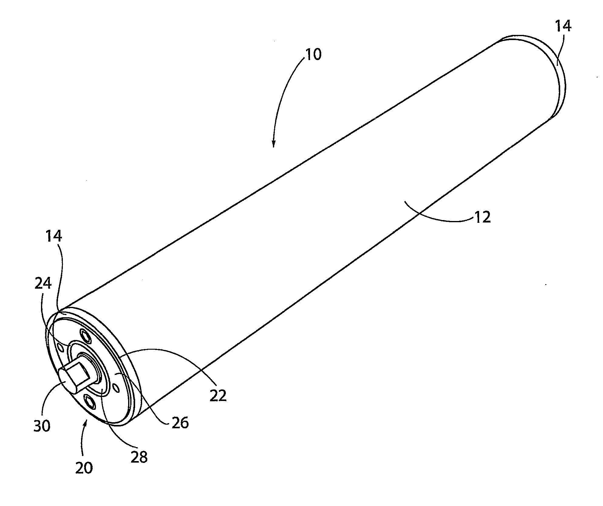
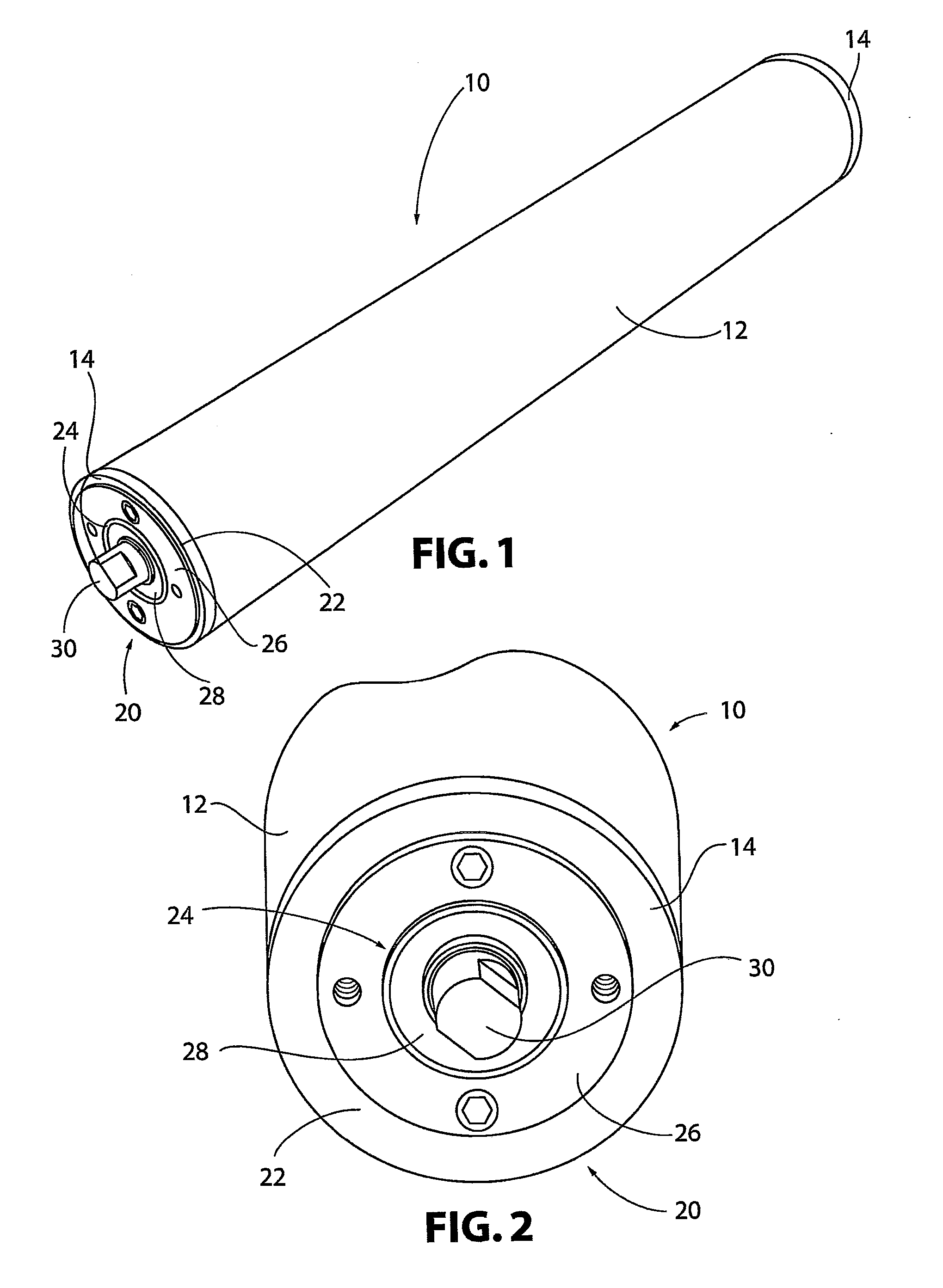
The present invention provides a rebuildable roller bearing assembly for rebuilding and replacing bearings or conveyor rollers without replacing the roller itself. The assembly includes a hub with an internal cavity and a central hole for receiving a stub shaft, and a removable roller bearing that can be easily replaced. The assembly also includes a dust cover for securing the assembly in a roller tube. The technical effects of this invention include improved durability, reduced downtime for maintenance, and reduced costs for replacing damaged parts.

Problems solved by technology

Because a new roller must be used each time a bearing on an existing roller fails or needs to be replaced, the cost of operating and maintaining the conveyor is significantly increased.
This becomes particularly evident in applications where the tubular roller shaft is significantly more expensive than the bearings located at its terminal ends.

Method used


Image

  • Rebuildable Roller and Roller Bearing Assembly for a Belt Line Conveyor System and a Method of Use Thereof
  • Rebuildable Roller and Roller Bearing Assembly for a Belt Line Conveyor System and a Method of Use Thereof
  • Rebuildable Roller and Roller Bearing Assembly for a Belt Line Conveyor System and a Method of Use Thereof

Examples


Embodiment Construction

[0040]For purposes of the description hereinafter, spatial orientation terms, if used, shall relate to the referenced embodiment as it is oriented in the accompanying drawing figures or otherwise described in the following detailed description. However, it is to be understood that the embodiments described hereinafter may assume many alternative variations and embodiments. It is also to be understood that the specific devices illustrated in the accompanying drawing figures and described herein are simply exemplary and should not be considered as limiting. As used herein, references to the “present invention” or “invention” relate to exemplary embodiments and not necessarily to every embodiment encompassed by the appended claims.

[0041]Referring to the drawings in which like reference characters refer to like parts throughout the several views thereof, a rebuildable conveyor roller bearing assembly is shown. The rebuildable conveyor roller includes a hollow, cylindrical roller tube ha...


PUM

PropertyMeasurementUnit
Angleaaaaaaaaaa
Diameteraaaaaaaaaa
Sizeaaaaaaaaaa

Abstract

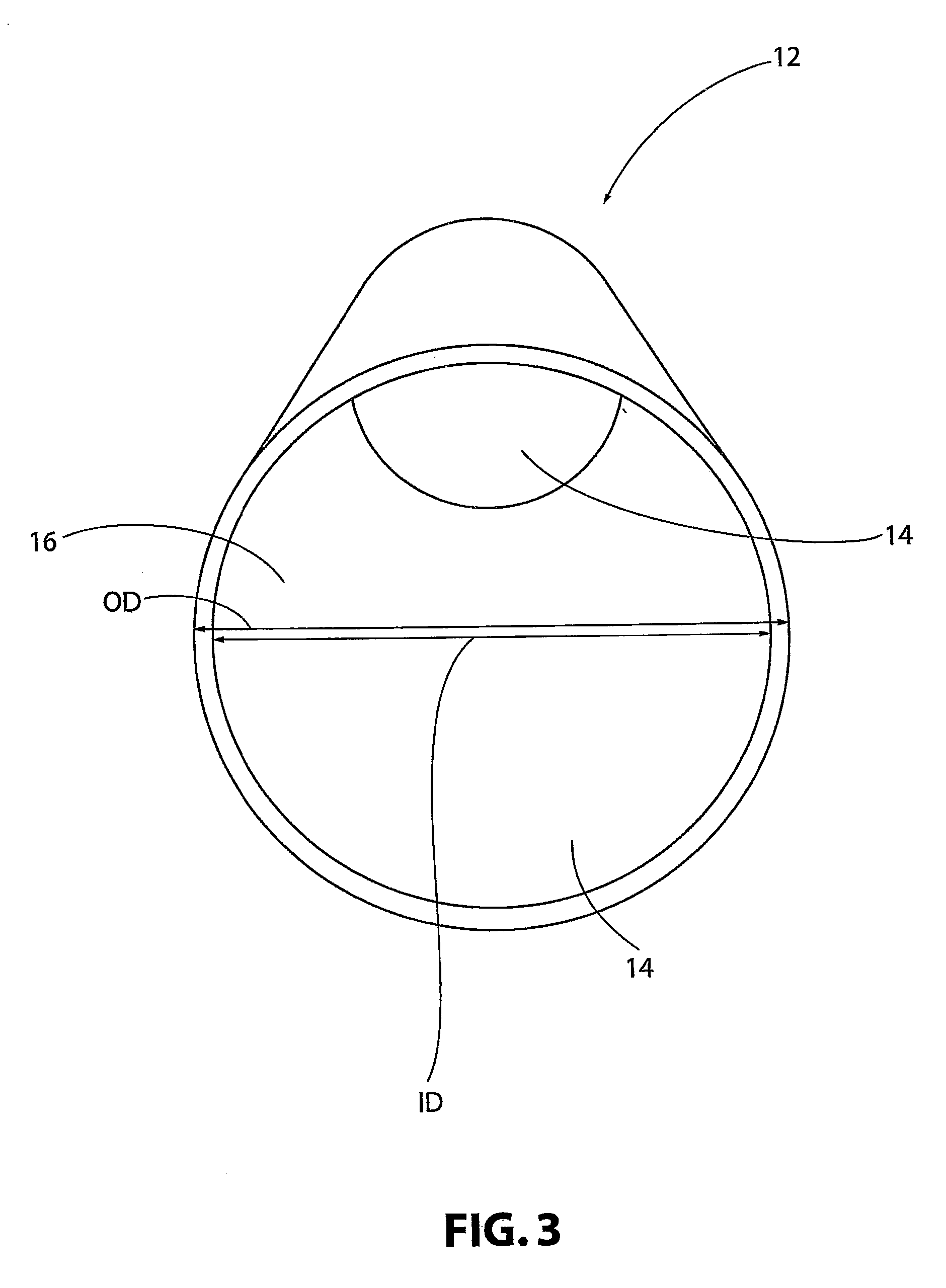
A rebuildable conveyor roller includes a hollow, cylindrical roller tube having a first end opposite a second end. The roller tube has a rebuildable conveyor roller bearing assembly provided at the first end and the second end. The rebuildable conveyor roller bearing assembly is affixed to the roller tube such that at least a part of the rebuildable conveyor roller bearing assembly is removable from the roller tube. A hub of the rebuildable conveyor roller bearing assembly has a generally circular shape that is dimensioned to fit inside the internal diameter of the roller tube. The hub has a centrally located hole through which a stub shaft may be inserted. A bearing holder is inserted in an internal cavity provided within the hub for securing the rebuildable conveyor roller bearing assembly to the roller tube.

Description

CROSS REFERENCE TO RELATED APPLICATION[0001]This application is based on U.S. Provisional Patent Application No. 61 / 566,131 filed on Dec. 2, 2011, on which priority of this patent application is based and which is hereby incorporated by reference in its entirety.BACKGROUND OF THE INVENTION[0002]1. Field of the Invention[0003]The present invention relates, in general, to devices and methods relating to a rebuildable conveyor roller. More specifically, the present invention is related to devices and methods for rebuilding or replacing roller bearings provided on terminal ends of a cylindrical conveyor roller.[0004]2. Description of the Related Art[0005]In a belt-type conveyor system, a plurality of rollers is rotatably supported on a stationary frame. Typically, the stationary frame includes a plurality of legs for elevating a main frame portion. The main frame portion generally includes two rails in a parallel arrangement. The plurality of rollers is rotatably supported in a space be...

Claims


Application Information

Patent Timeline
IPC IPC(8): B65G39/02B65G13/00F16C19/00
CPCB65G39/02F16C19/00B65G13/00B65G39/09Y10T29/49826F16C2237/00F16C35/077F16C13/022F16C2226/60F16C2326/58
Inventor KAMINSKI,, JR., MICHAEL RICHARD
Owner KAMINSKI JR MICHAEL RICHARD
Learn More