Eureka AIR delivers breakthrough ideas for toughest innovation challenges, trusted by R&D personnel around the world.

Light source chip and a thermally assisted head with the same, and manufacturing methods thereof

a technology of thermally assisted head and light source chip, which is applied in the direction of instruments, other domestic objects, transportation and packaging, etc., can solve the problems of laser diode chip even generating cracks on its surface, increasing the possibility of anti-reflection coating de-bonding from laser diode chip, and increasing the possibility of conventional laser diode chip manufacturing methods

Active Publication Date: 2013-05-30
SAE MAGNETICS (HK) LTD
View PDF0 Cites 7 Cited by
  • Summary
  • Abstract
  • Description
  • Claims
  • Application Information

AI Technical Summary

Benefits of technology

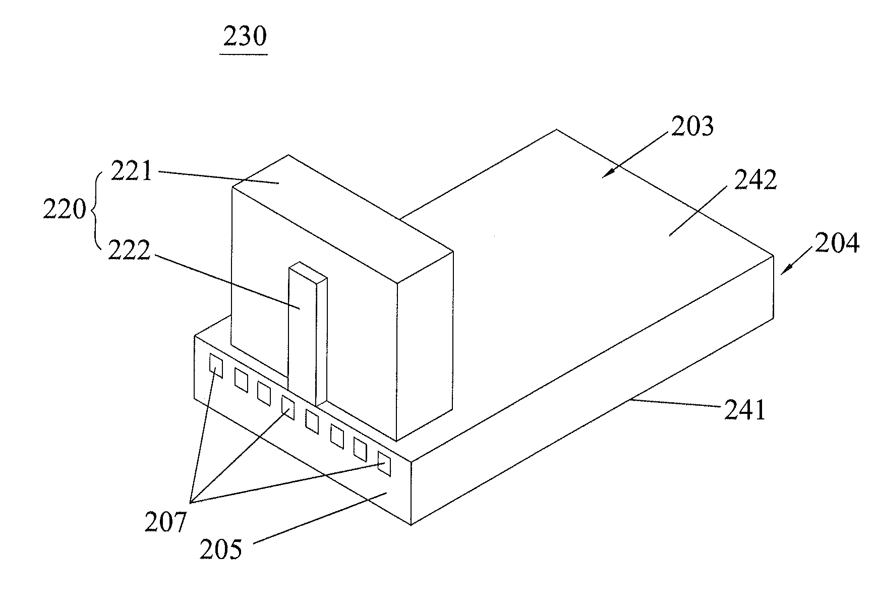
The present invention provides a manufacturing method for a light source chip for a thermally assisted head. The method results in a light source chip with a smooth edge and no cracks on the surface. The surface coating formed on the chip is hard to peel off. This improves the performance of the light source chip and ultimately the performance of the thermally assisted head. The manufacturing method includes forming blind holes on the light source bar by etching beforehand and then cutting the light source bar along every two adjacent blind holes using a cutting means with a smaller width than the blind hole. This ensures that the light source chip has a smooth edge and without any cracks. The method can improve the performance of the light source chip during the sequent machining process and results in a better performance of the thermally assisted head.

Problems solved by technology

However, the laser diode module made by the conventional method has several problems on the sequent machining processes which commonly include cleaning process, press process and transfer process and the like.
As the blade or laser beam cuts the laser diode bar directly, thus the cutting edge of the laser diode chip is rough, which may increase the possibility of the antireflection coating de-bonding from the laser diode chip.
Moreover, the laser diode chip even will generate some cracks on its surface under the action of some stress during the press process.
Therefore, the performances of the laser diode chip and the thermally assisted head are weakened which are undesired by the manufacturer and the consumer.

Method used


Image

  • Light source chip and a thermally assisted head with the same, and manufacturing methods thereof
  • Light source chip and a thermally assisted head with the same, and manufacturing methods thereof
  • Light source chip and a thermally assisted head with the same, and manufacturing methods thereof

Examples


Embodiment Construction

[0065]Various preferred embodiments of the invention will now be described with reference to the figures, wherein like reference numerals designate similar parts throughout the various views. As indicated above, the invention is directed to manufacturing methods of a thermally assisted head and a light source chip, by which a thermally assisted head with an improved light source module can be obtained, the light source chip thereof has a smooth edge and no cracks on its surface, and the surface coating formed thereon is hard to be peeled off, which improves the performance of the thermally assisted head.

[0066]FIG. 2 is a perspective view of a disk drive unit according to an embodiment of the invention. The disk drive unit 300 includes an HGA 200, a drive arm 304 connected to the HGA 200, a series of rotatable disks 301, and a spindle motor 302 to spin the disk 301, all of which are mounted in a housing 309. As shown in FIG. 3, the HGA 200 includes a suspension 290 and a thermally as...


PUM

PropertyMeasurementUnit
widthaaaaaaaaaa
widthaaaaaaaaaa
depthaaaaaaaaaa

Abstract

A manufacturing method of a light source chip for a thermally assisted head comprises steps of (a) providing a light source bar with a surface coating formed thereon; (b) forming several blind holes on the predetermined positions of the light source bar by etching, the blind hole having a top hollowed on the surface coating and a bottom hollowed on the light source bar, and the blind hole having a first biggest width at its top; (c) cutting the light source bar along every two adjacent blind holes by a cutting machine. The cutting machine has a cutting means with a second biggest width that is smaller than the first biggest width of the blind hole, thereby cutting down an individual light source chip without contacting the side edges of the blind hole.

Description

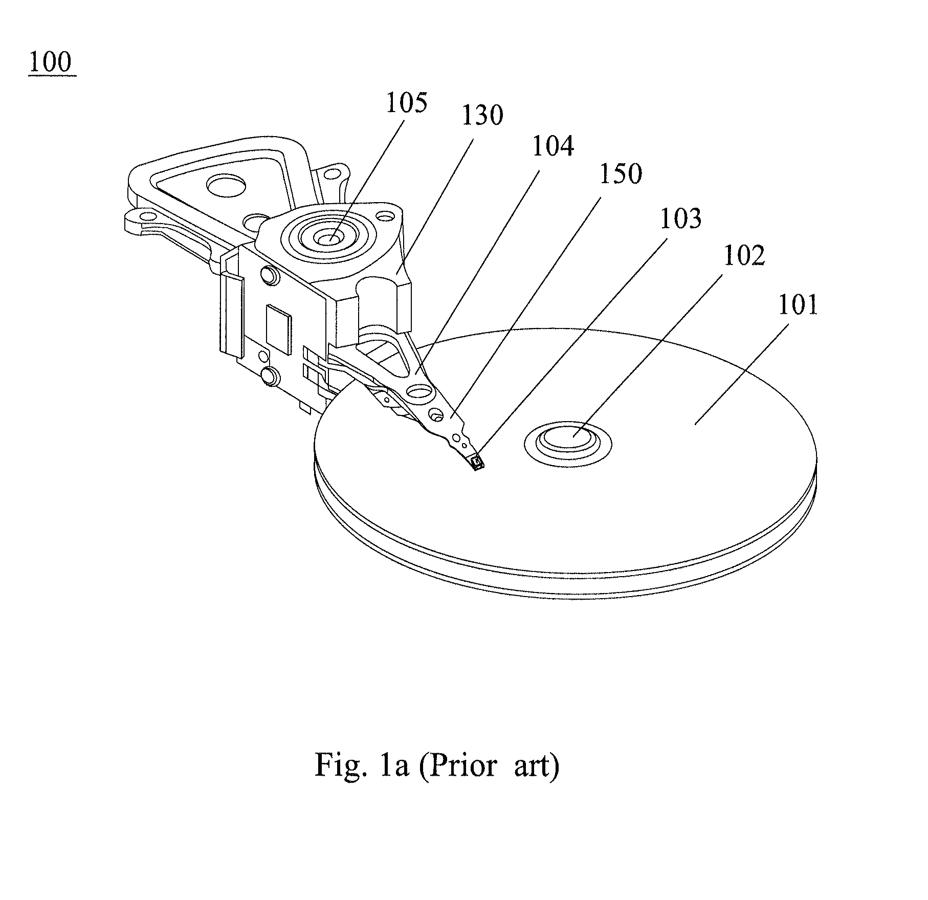
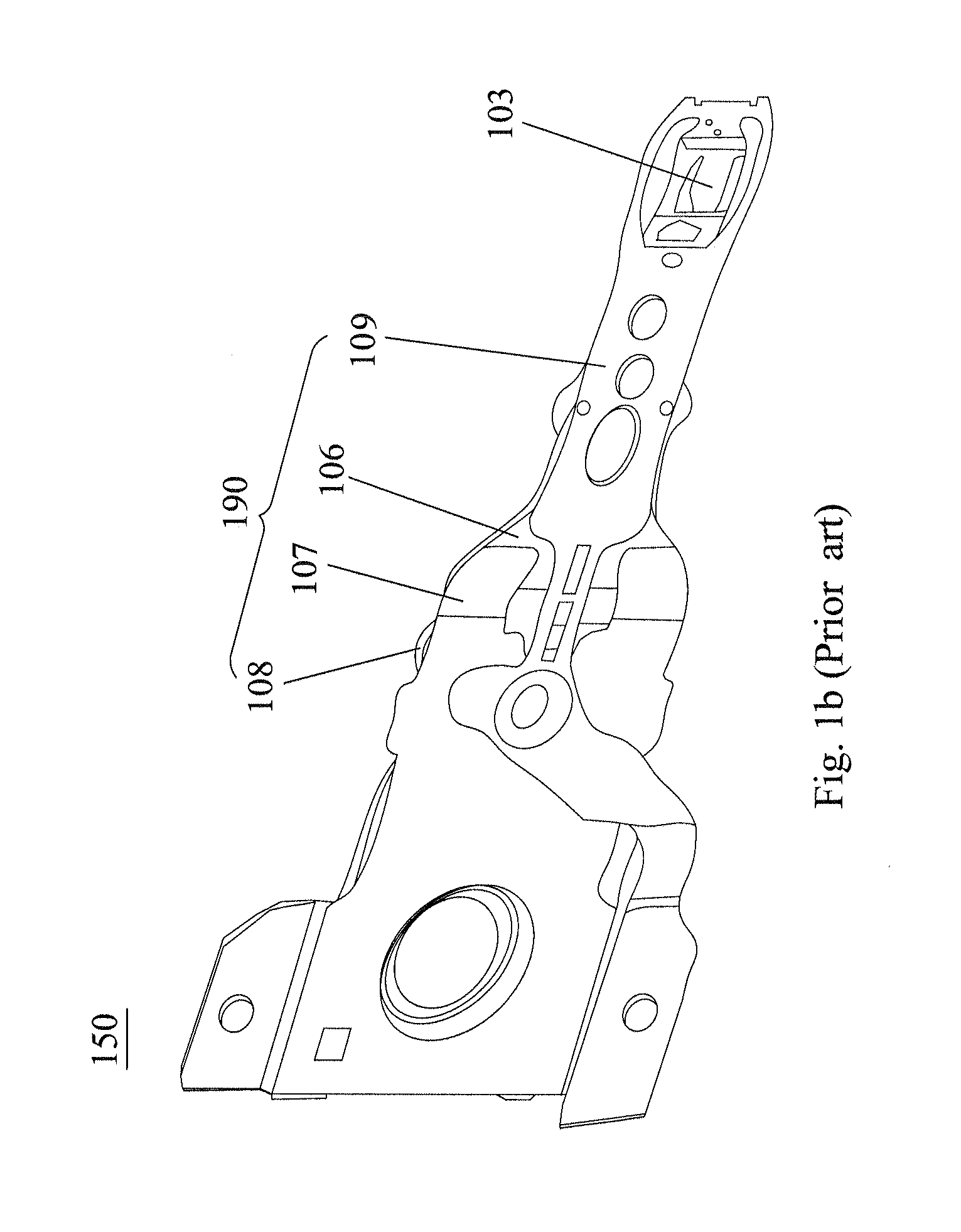
FIELD OF THE INVENTION[0001]The present invention relates to a thermally assisted head with a light source module and, more particularly, to a manufacturing method of a light source chip for a thermally assisted head, a manufacturing method of a thermally assisted head with the same, furthermore to a light source chip and a thermally assisted head formed by these methods.BACKGROUND OF THE INVENTION[0002]Hard disk drives are common information storage devices. FIG. 1a provides an illustration of a typical disk drive unit 100 essentially consisting of a series of rotatable disks 101 mounted on a spindle motor 102, and a Head Stack Assembly (HSA) 130 which is rotatable about an actuator arm axis 105 for accessing data tracks on disks during seeking. The HSA 130 includes at least one drive arm 104 a head gimbal assembly (HGA) 150. Typically, a spindling voice-coil motor (VCM) is provided for controlling the motion of the drive arm 104.[0003]Referring to FIG. 1b, the HGA 150 includes a t...

Claims


Application Information

Patent Timeline
Patent Type & Authority Applications(United States)
IPC IPC(8): B32B7/02B32B3/00G11B7/22B32B3/02
CPCG11B13/04G11B5/102G11B2005/0021Y10T29/49032Y10T428/24942Y10T428/23Y10T428/24612
Inventor FUJII, RYUJILEE, TAI BOONTANZAWA, HIDEKIKONAKAWA, YASUHIRO
Owner SAE MAGNETICS (HK) LTD
Why Eureka
Eureka Blog
Learn More