
Insulated wire

Inactive Publication Date: 2013-05-23
HITACHI METALS LTD
View PDF4 Cites 11 Cited by
  • Summary
  • Abstract
  • Description
  • Claims
  • Application Information

AI Technical Summary

Benefits of technology

This patent is about a type of insulated wire that has excellent resistance to heat and can withstand high levels of electricity discharge.

Problems solved by technology

In addition, high voltages (such as surge voltages from an inverter) applied to a coil may generate partial discharges, thus potentially degrading or damaging the insulation coating.
However, generally, insulation coatings made of a fluorine-containing polyimide resin have poor adhesion to wire conductors.
Thus, an insulation coating made of the fluorine-containing polyimide resin of the JP-A 2002-56720 may be lifted off from a wire conductor by severe mechanical stresses caused by harsh processes such as winding, which leads to a degradation of the partial discharge inception voltage of the insulated wire.
In the JP-A 2005-106898 insulated wire, more than half of the extruded insulation layer other than the innermost layer is made of polyphenylene sulfide resin whose melting point is approximately 280° C. Therefore, when the temperature of the insulated wire exceeds about 300° C. even locally, the extruded insulation layer containing the polyphenylene sulfide resin may be significantly deformed and may not maintain its electrical insulation properties.
Thus, the insulated wire of this disclosure may have a problem of poor thermal resistance.
Also, coil wires tend to be wound more densely to obtain higher filling factors, and, as a result, insulated wires are prone to be overheated locally during electrical equipment operation.
When the temperature of insulated wires rises even locally, decreases the partial discharge inception voltage of the overheated local portions of the wire, thus degrading the electrical insulation properties of the wire.

Method used


Image

  • Insulated wire
  • Insulated wire

Examples


examples

[0046]The present invention will be described in more detail below with reference to examples. However, the invention is not limited to the specific examples described below.

preparation of examples 1 to 9

and Comparative Examples 1 to 3

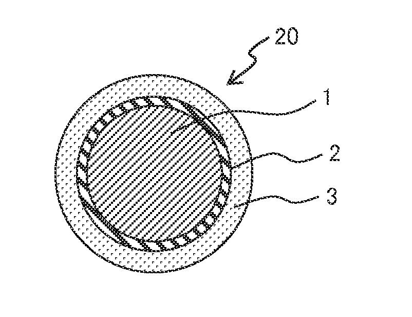
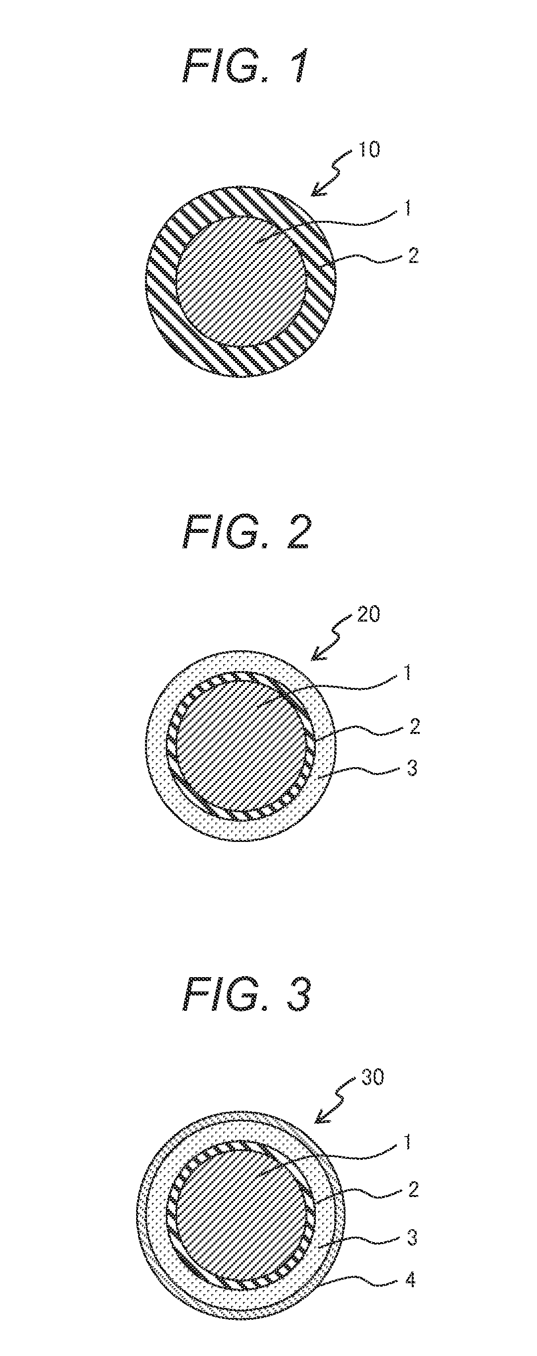
[0047]Each of resin compositions of Examples and Comparative examples shown in Table 1 was extrusion-coated around a 1.25 mm diameter copper conductor using an extruder to form an insulated wire as shown in FIG. 1. The extrusion temperature was approximately 360° C., and the thickness of the insulation layer (the first extrusion coated layer) was approximately 100 μm. Table 1 shows contents of the resin composition used to form the extrusion coated layer of Examples 1 to 9 and Comparative examples 1 to 3. The apparent viscosity of the resins (A) in Table 1 was measured at a shear rate of 10 sec−1 at 380° C. using a capillary rheometer (CAPIROGRAPH 1B available from TOYO SEIKI Co., Ltd.).

TABLE 1Contents of Resin Composition for Extrusion Coated Layerof Examples 1 to 9 and Comparative Examples 1 to 3.ExampleResin composition123456ContentsResinPolyether ether ketone2550————(Parts(A)(Apparent viscosity = 2000 Pa · s)by mass)Polyether ether ketone——25202010...


PUM

PropertyMeasurementUnit
Temperatureaaaaaaaaaa
Viscosityaaaaaaaaaa
Viscosityaaaaaaaaaa

Abstract

There is provided an insulated wire including a wire conductor and at least one extruded insulation layer formed on the wire conductor. The at least one extruded insulation layer is made of a phase separated resin composition including: a resin (A) including polyether ether ketone as a continuous phase; and a resin (B) with a relative dielectric constant of 2.6 or less as a dispersed phase.

Description

CLAIM OF PRIORITY[0001]The present application claims priority from Japanese patent application serial no. 2011-252278 filed on Nov. 18, 2011, the content of which is hereby incorporated by reference into this application.BACKGROUND OF THE INVENTION[0002]1. Field of the Invention[0003]The present invention relates to insulated wires used for coils in electrical equipment such as rotary electric machines and transformers. More particularly, the invention relates to insulated wires covered with at least an extrusion coated insulation layer.[0004]2. Description of Related Art[0005]Insulated or enameled wires are used for coils in electrical equipment such as rotary electric machines and transformers. Such insulated wires are typically formed by applying one or more insulation coatings around a metal conductor having a desired cross section (such as circular and rectangular) depending on the shape and application of the coil. Typically, insulation coatings are formed by the following tw...

Claims


Application Information

Patent Timeline
IPC IPC(8): H01B3/42H01B7/02
CPCH01B3/427H01B7/0275Y10T428/2933H01B3/442H01B3/441
Inventor YAMAZAKI, TAKANORIMOMOSE, HIDETOMORISHITA, SHIGEHIRO
Owner HITACHI METALS LTD
Learn More