
Dry Etching Agent and Dry Etching Method

a technology of dry etching agent and dry etching method, which is applied in the direction of electrical equipment, chemical instruments and processes, organic chemistry, etc., can solve the problems of difficult production of alternative compounds, high gwp content of products, and inability to meet the requirements of high gwp, etc., to achieve efficient etching of silicon material layers, high etching rate, and high selectivity

Active Publication Date: 2013-05-02
CENT GLASS CO LTD
View PDF5 Cites 22 Cited by
  • Summary
  • Abstract
  • Description
  • Claims
  • Application Information

AI Technical Summary

Benefits of technology

The present inventors have developed a new dry etching agent using 1,3,3,3-tetrafluoropropene (CF3CH═CFH) which has advantages over traditional etching agents. This new agent has the ability to generate a good processing shape and is less harmful to the environment. The etching agent can be mixed with other gases such as H2, O2, O3, CO, CO2, CF3OF, COF2, NO2, F2, NF3, Cl2, Br2, I2, CH4, C2H2, C2H4, C2H6, C3H4, C3H6, C3H8, HF, HI,HBr,HCl, NO, NH3, YFn, and inert gases such as N2, He, Ar, and can efficiently etch silicon materials with high selectivity and etching rates. The use of 1,3,3,3-tetrafluoropropene as a dry etching agent is advantageous because it has a CF3CH structure that easily generates CF3+ ions, as well as a double bond and hydrogen atoms that can form polymer chains, which helps protect the walls and allows for anisotropic etching. Additionally, 1,3,3,3-tetrafluoropropene has a single unsaturated double bond in the molecule, making it highly degradable by OH radials and having a small impact on the global environment. The dry etching agent is usable for practical applications with no problem and is very beneficial for both industrial and environmental perspectives.

Problems solved by technology

Although the perfluoroketone, hydrofluoro ether and hydrofluoro vinyl ether are known as alternatives to the PFC and HFC compounds, these alternative compounds have the problems that: when the alternative compound gets decomposed, the resulting decomposition product contains a considerable amount of high-GWP PFC compound; and the alternative compound is not easy to produce and is not economical.
Any of the techniques using the conventional etching gases requires complicated process and equipment, limited temperature conditions and operations such as application of vibration to the substrate and gas as in the case of Patent Document 5 and thus presents the problem of a narrow process window.

Method used


Image

  • Dry Etching Agent and Dry Etching Method
  • Dry Etching Agent and Dry Etching Method

Examples


examples

[0081]The present invention will be described in more detail below by way of the following examples. It should be noted that these examples are illustrative and are not intended to limit the present invention thereto.

[0082]In Examples 1 to 10, the dry etching agent according to the present invention was applied for contact-hole processing to perform etching treatment on an interlayer dielectric film (SiO2) or a silicon nitride film. In comparison, etching treatment was performed using CF4 as a perfluorocarbon, F2 or C4F6 (CF2═CF—CF═CF2) as a diolefin in Comparative Examples 1 to 12.

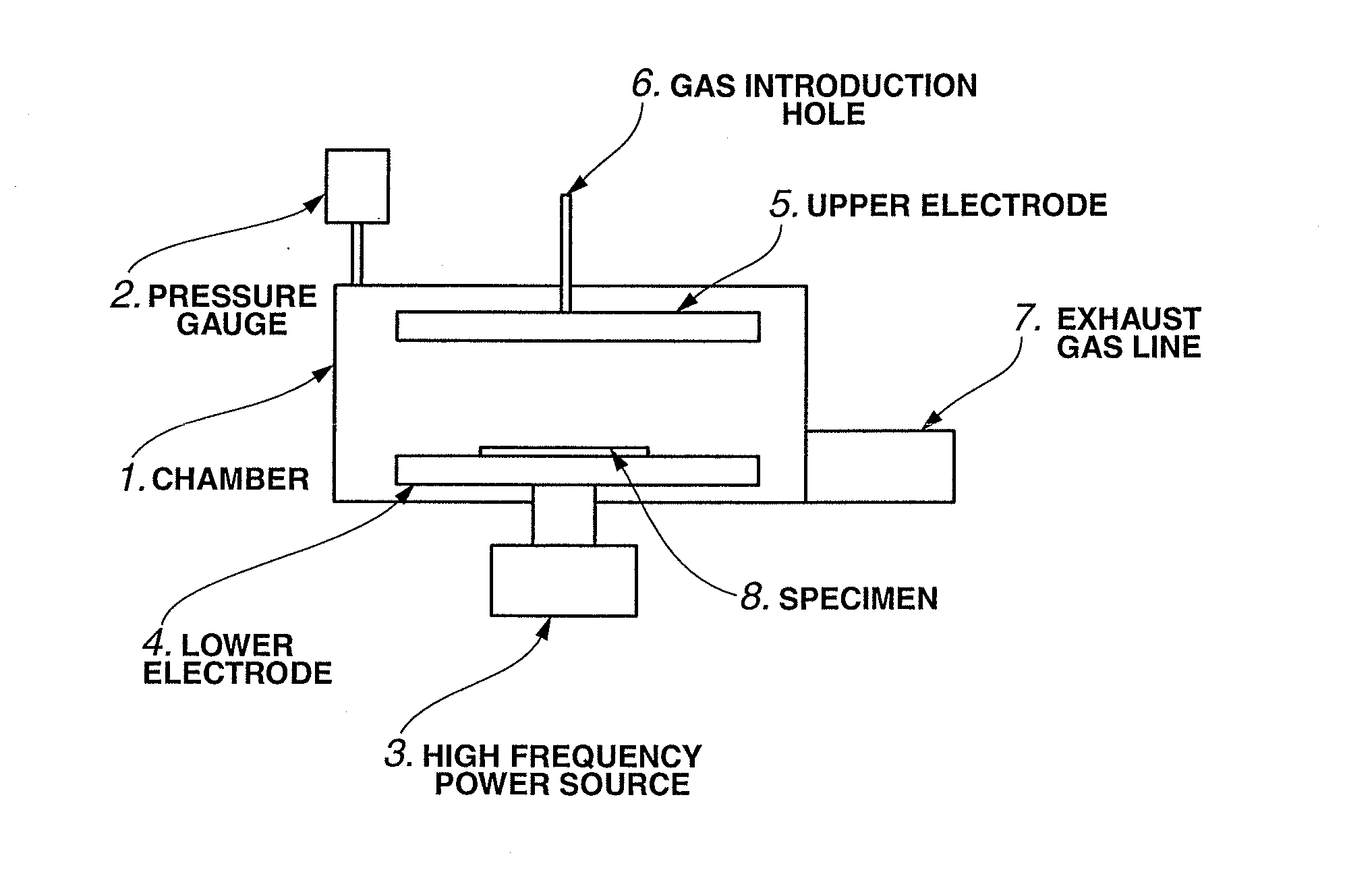
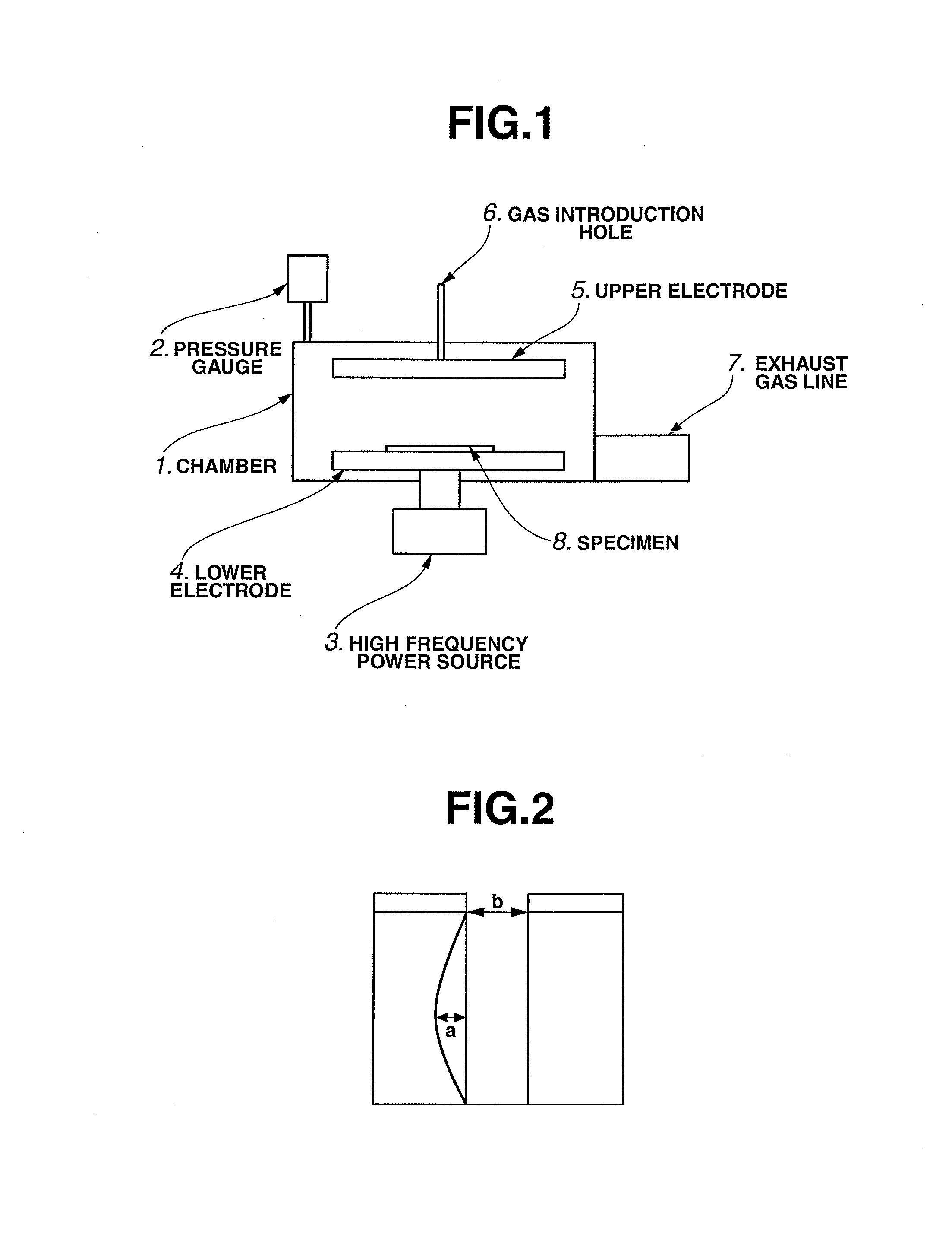
[0083]FIG. 1 is a schematic view of an experimental device used in the respective examples.

[0084]In the experimental device, a process gas was introduced into a chamber 1 through a gas introduction hole 6 that was connected to an upper electrode 5 in the chamber 1. Subsequently, the pressure inside the chamber 1 was set to 2Pa. The process gas was then excited by means of a high frequency power source 3 (...


PUM

PropertyMeasurementUnit
Fractionaaaaaaaaaa
Percent by volumeaaaaaaaaaa
Fractionaaaaaaaaaa

Abstract

A dry etching agent according to the present invention preferably contains: (A) 1,3,3,3-tetrafluoropropene; (B) at least one kind of additive gas selected from the group consisting of H2, O2, O3, CO, CO2, COCl2, COF2, CF3OF, NO2, F2, NF3, Cl2, Br2, I2, CH4, C2H2, C2H4, C2H6, C3H4, C3H6, C3H8, HF, HI, HBr, HCl, NO, NH3 and YFn (where Y represents Cl, Br or I; and n represents an integer satisfying 1≦n≦7); and (C) an inert gas. This dry etching agent has less effect on the global environment and can obtain a significant improvement in process window and address processing requirements such as low side etching ratio and high aspect ratio even without any special substrate excitation operation.

Description

TECHNICAL FIELD[0001]The present invention relates to a dry etching agent containing 1,1,1,3-tetrafluoropropene and a dry etching method using the dry etching agent.BACKGROUND ART[0002]In response to the recent demand for very fine processing techniques in the field of semiconductor manufacturing, dry etching has become mainstream in place of wet processing. The dry etching is a technique for forming a fine pattern on a molecular basis on a material surface by generation of plasma in a vacuum space.[0003]For etching of semiconductor material e.g. silicon dioxide (SiO2), perfluorocarbon (PFC) and hydrofluorocarbon (HFC) compounds such as CF4, CHF3, C2F6, C3F8 and C4F8 have been used as etching agents in order to increase the etching rate of SiO2 relative to substrate material e.g. silicon, polysilicon or silicon nitride. However, these PFC and HFC compounds are specified as emission control materials in the Kyoto protocol (COP3) because each of these PFC and HFC compounds has a long ...

Claims


Application Information

Patent Timeline
IPC IPC(8): C09K13/00
CPCH01L21/31116C09K13/08C09K13/00C07C21/18H01L21/3065
Inventor UMEZAKI, TOMONORIHIBINO, YASUOMORI, ISAMUOKAMOTO, SATORUKIKUCHI, AKIOU
Owner CENT GLASS CO LTD
Learn More