
Narrow band fluorophore exciter

Inactive Publication Date: 2013-05-02
BENNETT GORDON +1
View PDF6 Cites 7 Cited by
  • Summary
  • Abstract
  • Description
  • Claims
  • Application Information

AI Technical Summary

Benefits of technology

The present invention provides a system and methods for a solid-state light source based on an LED array driven by a constant current power source with an active feedback control. This system can be used as an efficient and stable alternative to existing light sources such as broadband mercury vapor bulbs and plasma-based light sources in fluorescent identification and measurement systems such as microscopy and flow cytometry. The invention offers durability, stability, reduced operating expenses, reduced variance of output, and increased accuracy of frequency and amplitude. This system will provide benefits as the excitation mechanism in these applications. Thus, the present invention aims to stabilize the excitation mechanism and eliminate variations introduced by other light sources.

Problems solved by technology

It does not teach or describe a method or system for a bandwidth tailored solid state light source of high stability.
The microscope utilizes conventional confocal optics optimized to have a very narrow depth of field, thus limiting the information collected to a thin planar region.
It does not teach or describe a method or system for a bandwidth tailored solid state Light Emitting Diode array light source of high stability.

Method used


Image

  • Narrow band fluorophore exciter
  • Narrow band fluorophore exciter
  • Narrow band fluorophore exciter

Examples


Embodiment Construction

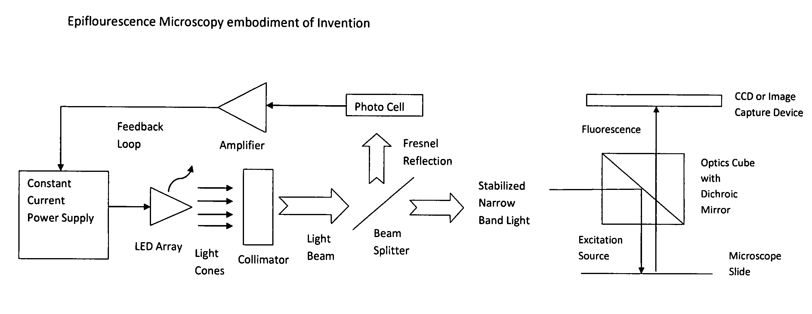
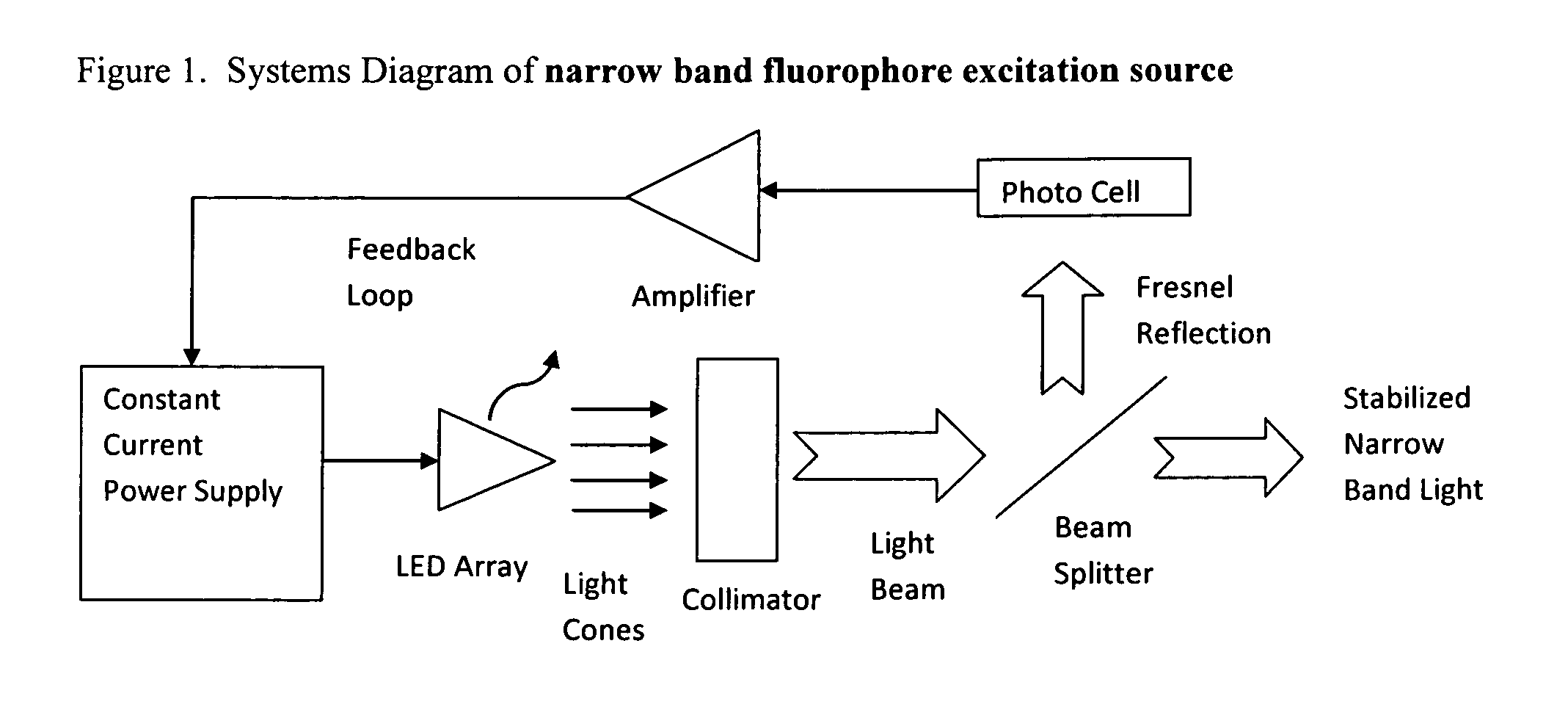
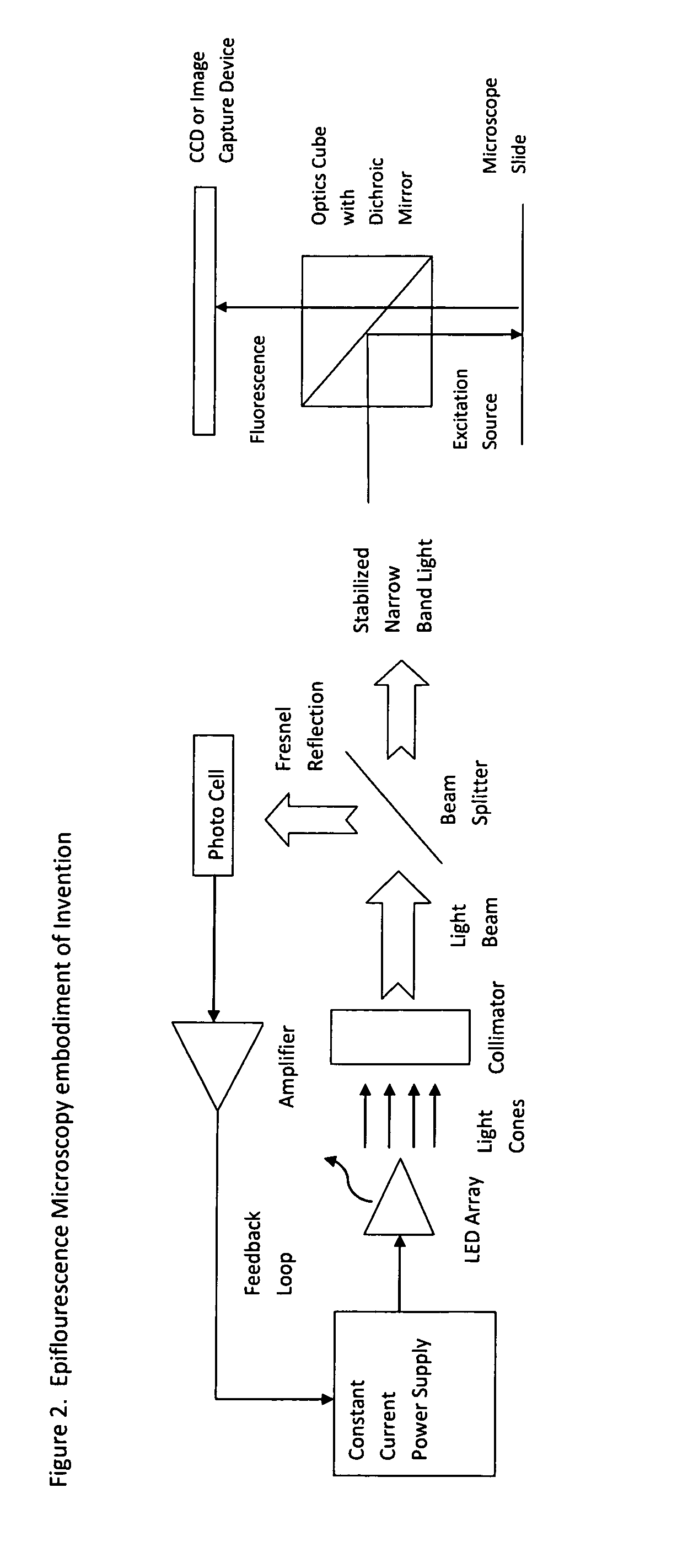
[0035]FIG. 1 shows a systems diagram of the best mode for carrying out the invention contemplated by the inventors of the solid state constant feedback light emitting diode (LED) narrow band fluorophore exciter. It is a solid-state light source based on a light emitting diode (LED) array of unique geometry driven by a constant current power source with active feedback control. This system can be implemented for broad frequency ranges or for narrow band frequencies depending on the characteristics of the LEDs chosen to populate the array and the geometry of the array. The invention can be used as an excitation light source for fluorescent microscopy and flow cytometry applications as an efficient and stable alternative to existing light sources such as broadband mercury vapor bulbs and plasma-based light sources. Benefits of the current invention include: durability; stability; reduced operating expenses; reduced variance of output; and increased accuracy of frequency and amplitude. ...


PUM


Abstract

Disclosed is a solid-state light source based on a light emitting diode (LED) array driven by a constant current power source with an active feedback control. This system can be implemented for broad frequency ranges or for narrow band frequencies depending on the characteristics of the LEDs chosen to populate the array and the geometry of the array. The invention can be used as an excitation light source for fluorescent microscopy and flow cytometry applications as an efficient and stable alternative to existing light sources such as broadband mercury vapor bulbs and plasma-based light sources. Benefits of the current invention include: durability; stability; reduced operating expenses; reduced variance of output; and increased accuracy of frequency and amplitude. This system will provide benefits as the excitation mechanism in fluorescent identification and measurement systems such as microscopy and flow cytometry.

Description

BACKGROUND OF THE INVENTION[0001]1. Field of the Invention[0002]The present invention is a system and methods for a solid-state light source based on a light emitting diode (LED) array driven by a constant current power source with an active feedback control. This system can be implemented for broad frequency ranges or for narrow band frequencies depending on the characteristics of the LEDs chosen to populate the array and the geometry of the array.[0003]2. Description of the Prior Art[0004]U.S. Pat. No. 7,564,622 describes a method for making A microscope that enables a phase object or surface pits and projections to be observed at a relatively low image-formation magnification of 4 or lower over a wide viewing range yet in a relatively narrow spatial frequency distribution range. The microscope comprises a light source, an illumination optical system, a partial aperture located at the pupil position of the illumination optical system, an image-formation optical system, and an eyep...

Claims


Application Information

Patent Timeline
IPC IPC(8): G01N21/64H05B37/02
CPCG01N2201/062G01N21/6458
Inventor BENNETT, GORDONCOUSINS, JOHN J.
Owner BENNETT GORDON
Learn More