Superjunction semiconductor device
a semiconductor device and superjunction technology, applied in the direction of semiconductor devices, basic electric elements, electrical appliances, etc., can solve the problems of reducing the reliability of long-term breakdown voltage, difficulty in achieving a structure wherein, and increasing the on-state current, so as to improve the long-term breakdown voltage reliability, improve the charge resistance of the element peripheral portion, and improve the trade-off relationship between breakdown voltage characteristics and voltage drop characteristics.
- Summary
- Abstract
- Description
- Claims
- Application Information
AI Technical Summary
Benefits of technology
Problems solved by technology
Method used
Image
Examples
embodiment 1
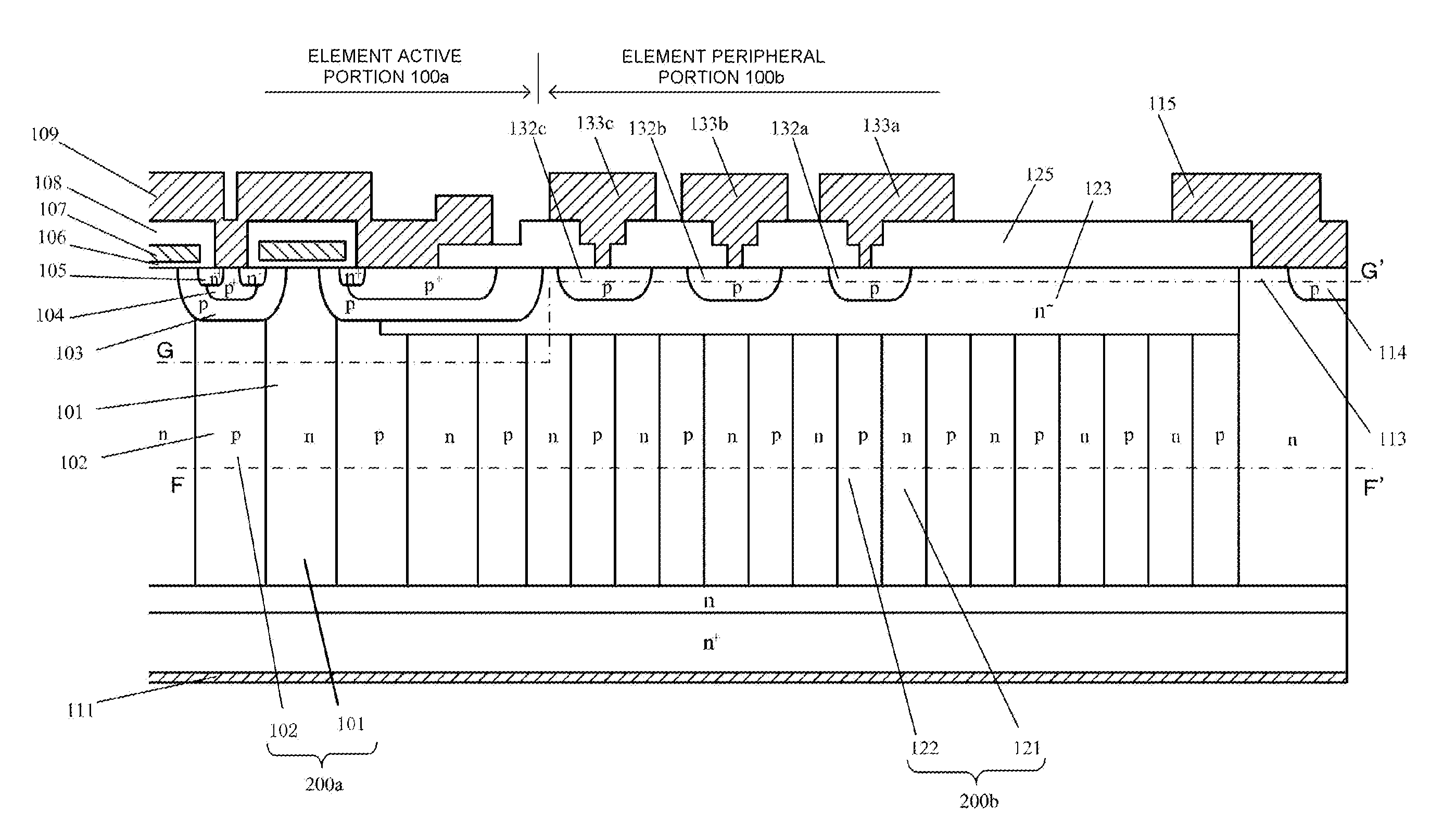
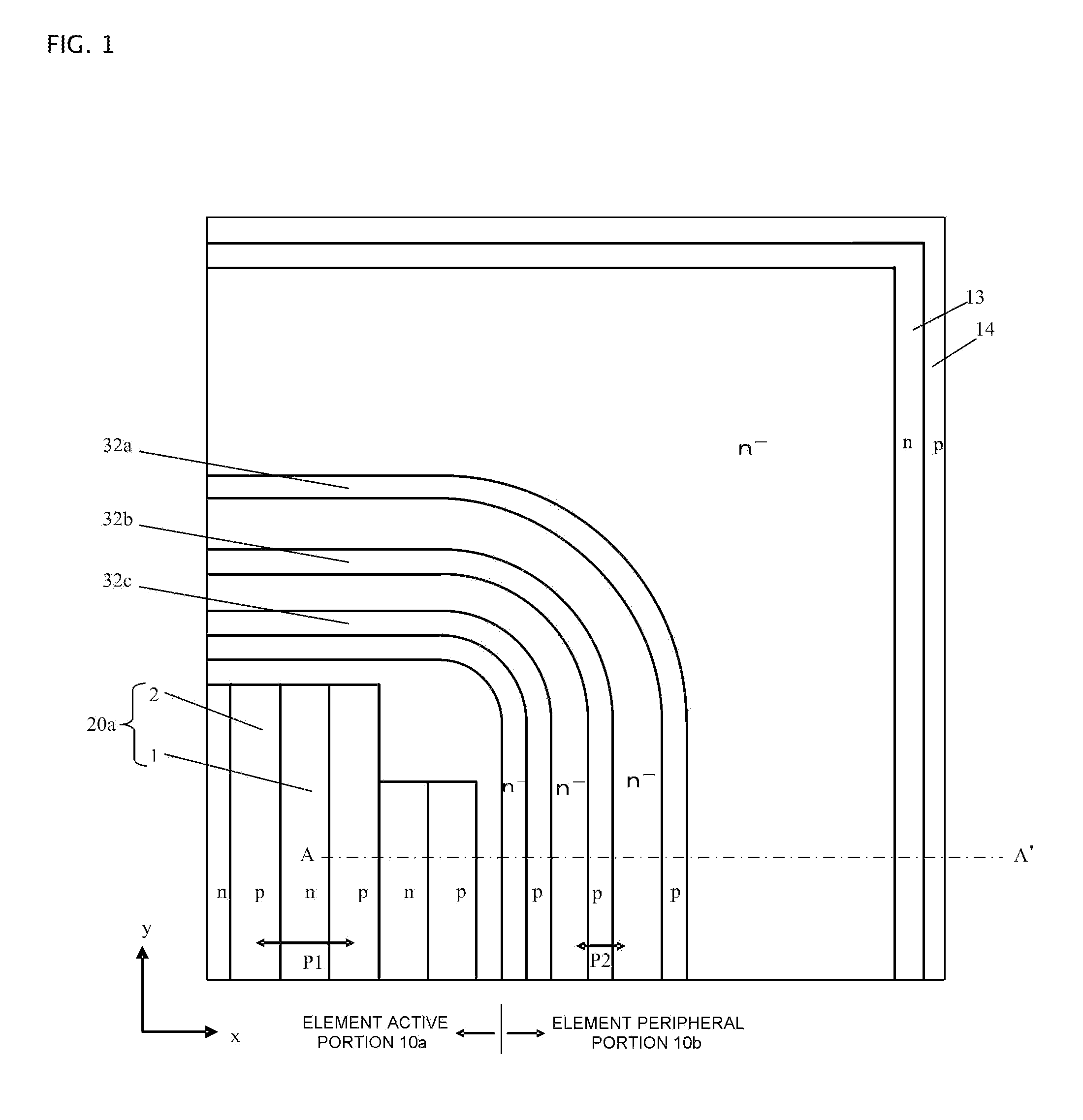
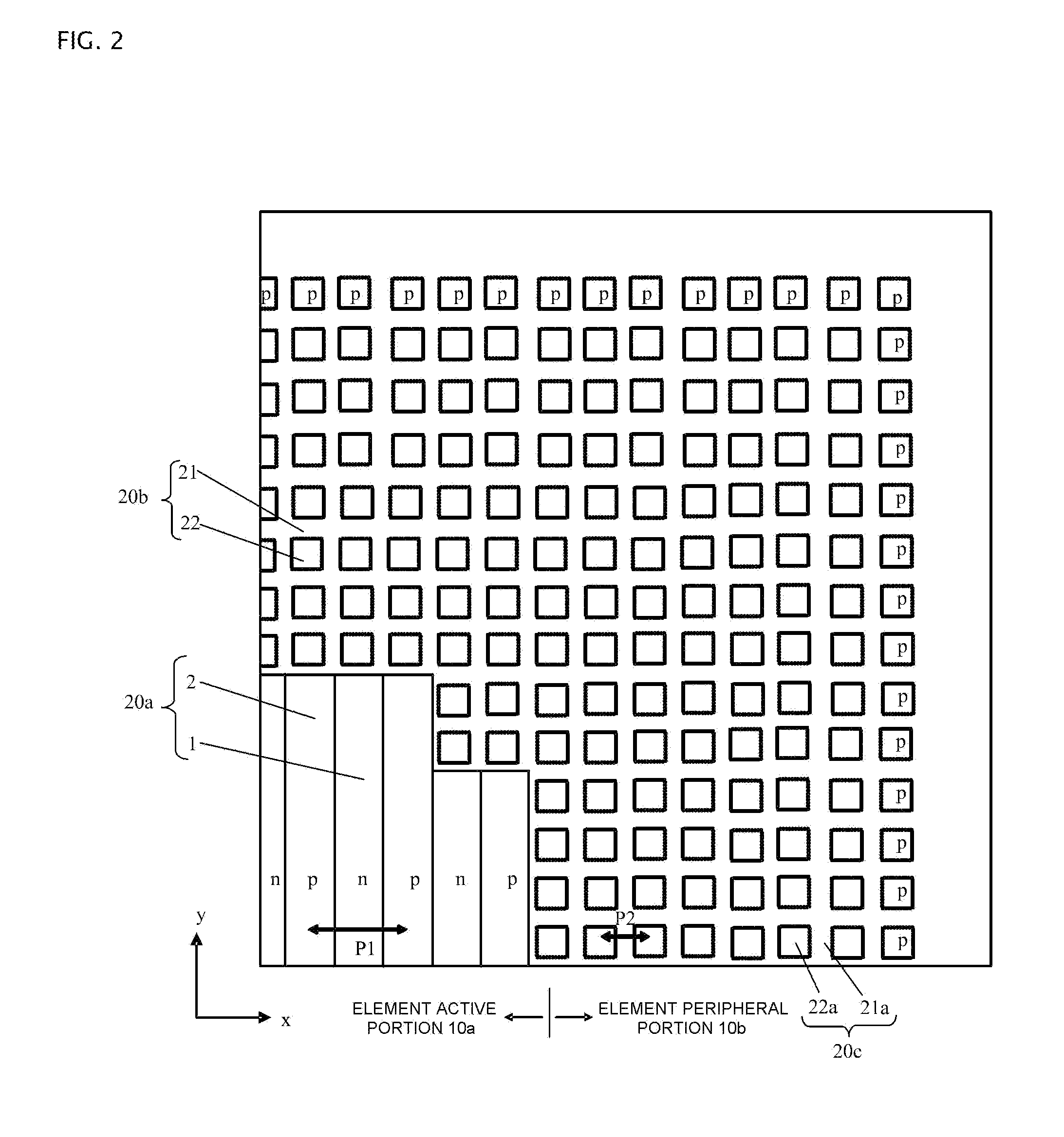
[0031]FIGS. 1, 2, 3, and 4 each show a plan view or sectional view of a vertical superjunction MOSFET (hereafter, element) according to Embodiment 1 of the invention. FIG. 1 shows one portion (a one-fourth element of a quadrilateral chip cut into four equal portions by two perpendicular lines passing through the center of the chip) of a plan view of the element wherein, for ease of understanding, only underlying parallel pn layer 20a is shown in element active portion 10a, while a MOS surface structure disposed in the surface layer of parallel pn layer 20a and source electrode 9 are omitted. FIG. 1 can also be said to be an internal plan view cut along a surface B-B′ (a surface parallel to the main surface) in FIG. 4, to be described hereafter. Element active portion 10a and, as element peripheral portion 10b encircling element active portion 10a, substrate surface p-type guard rings 32a, 32b, and 32c, n− region 23, n-type channel stopper 13 positioned on the outermost side, and p-t...
embodiment 2
[0045]FIG. 11 shows one portion (a one-fourth element) of a transparent plan view of a superjunction MOSFET of Embodiment 2 according to the superjunction semiconductor device of the invention. Although FIG. 11 is the same kind of internal plan view as FIG. 2, it is made a transparent view by a depiction of p-type guard rings 32a, 32b, and 32c being added. In the superjunction MOSFET shown in FIG. 11, the plane pattern of the parallel pn layer of element peripheral portion 10b being of a striped form differs from the superjunction MOSFET of FIG. 2, while other structures are the same as those in FIG. 2. That is, as opposed to Embodiment 1, the plane pattern of parallel pn layers 20b and 20c of element peripheral portion 10b is of a striped form rather than a lattice form, and the depth of p-type partition region 22a is reduced only on the outer peripheral side in element peripheral portion 10b. By reducing the depth of p-type partition region 22a, regardless of the form of parallel ...
PUM
 Abstract
Description
Claims
Application Information
 - R&D
- Intellectual Property
- Life Sciences
- Materials
- Tech Scout
- Unparalleled Data Quality
- Higher Quality Content
- 60% Fewer Hallucinations
Browse by: Latest US Patents, China's latest patents, Technical Efficacy Thesaurus, Application Domain, Technology Topic, Popular Technical Reports.
© 2025 PatSnap. All rights reserved.Legal|Privacy policy|Modern Slavery Act Transparency Statement|Sitemap|About US| Contact US: help@patsnap.com


