Ceramic composite for light conversion, process for production thereof, and light-emitting devices provided with same

Active Publication Date: 2013-04-11
UBE IND LTD
View PDF2 Cites 6 Cited by
  • Summary
  • Abstract
  • Description
  • Claims
  • Application Information

AI Technical Summary

Benefits of technology

The patent describes a ceramic material that can convert light, even when increased quantities of certain elements are used to adjust its fluorescence peak wavelength. The ceramic material can maintain a high level of light output, and a method for producing it is also provided. Additionally, a light emitting device that uses this ceramic material is also described.

Problems solved by technology

However, in the case of the structures of now commonly used white light emitting diodes typified by Patent Literature 1, a powdered phosphor is mixed with a resin such as epoxy, and applied, thus, it is difficult to ensure homogeneity in the mixing state of the powdered phosphor and the resin, and control stabilization or the like of the thickness of the applied film, and it is pointed out that the white light emitting diodes are likely to cause color unevenness or variability.
In addition, the resin required in the case of using the powdered phosphor is inferior in heat resistance as compared with metals or ceramics, and thus likely to cause a decrease in transmittance due to the resin modified by heat from the light emitting element.
Therefore, this decrease in transmittance is problematic for higher outputs of white light emitting diodes required now.

Method used


Image

  • Ceramic composite for light conversion, process for production thereof, and light-emitting devices provided with same
  • Ceramic composite for light conversion, process for production thereof, and light-emitting devices provided with same
  • Ceramic composite for light conversion, process for production thereof, and light-emitting devices provided with same

Examples


example 1

[0064]An α-Al2O3 powder (purity: 99.99%), a Y2O3 powder (purity: 99.9%), and a CeO2 powder (purity: 99.9%) were weighed respectively so as to provide (x′=) 0.7975 mol in terms of AlO3 / 2, (y′=) 0.2025×(a′=) 0.996 mol in terms of YO3 / 2, and (y′=) 0.2025×(c′=) 0.004 mol. These powders were subjected to wet mixing in ethanol for 16 hours by means of a ball mill, and then to the removal of ethanol as a solvent with the use of an evaporator to obtain a raw material powder. The raw material powder was preliminarily dissolved in a vacuum furnace to provide a raw material for unidirectional solidification.

[0065]Next, this raw material was directly put in a molybdenum crucible, the molybdenum crucible was set in a dissolution holding zone of an unidirectional solidification apparatus provided with the dissolution holding zone in an upper section and a cooling zone with a temperature gradient of 100° C. / cm set in the vertical direction (solidification direction) in a lower section, and the raw...

example 2

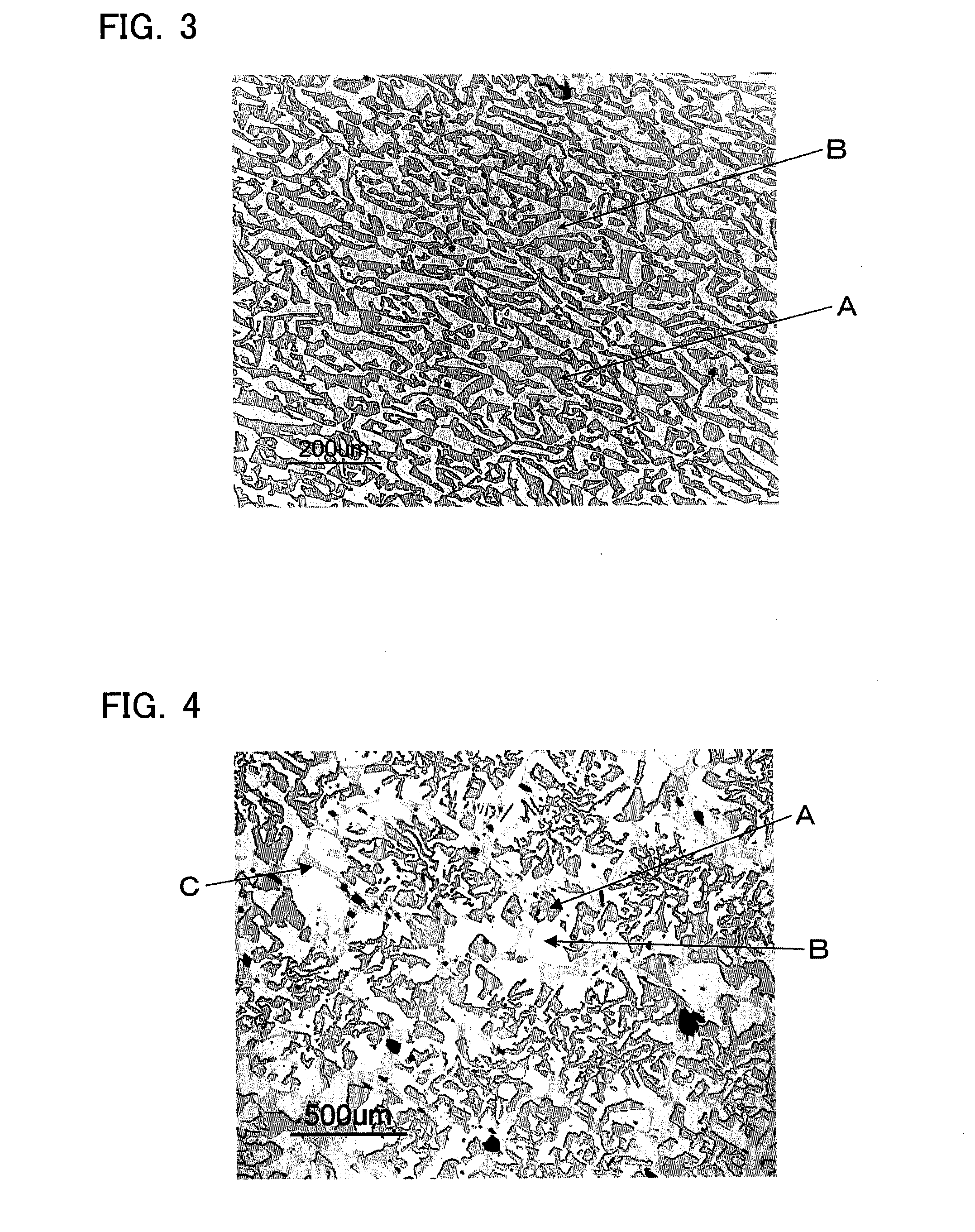
[0076]Except that α-Al2O3 powder (purity: 99.99%), a Y2O3 powder (purity: 99.9%), and a CeO2 powder (purity: 99.9%) were used as raw materials respectively for 0.7857 mol in terms of AlO3 / 2, 0.2143×0.993 mol in terms of YO3 / 2, and 0.2143×0.007 mol, and that the lowering speed of the molybdenum crucible was adjusted to 5 mm / hour, a solidification product according to Example 2 was obtained by the same process as in Example 1. FIG. 3 shows a micrograph of a sectional texture perpendicular to the solidification direction in the portion of the solidification product other than a skin thereof. A black section A corresponds to the second phase (Al2O3 phase), whereas a white section B corresponds to the first phase (YAG:Ce phase).

[0077]As in the case of Example 1, the x, y, a, and c in the formula (1), the total area (% by area) of the first phase and second phase to the entire cross section of the solidification product, the fluorescence peak wavelength (nm), Cy, and the total radiant flu...

example 3

[0078]Except that α-Al2O3 powder (purity: 99.99%), a Y2O3 powder (purity: 99.9%), and a CeO2 powder (purity: 99.9%) were used as raw materials respectively for 0.7857 mol in terms of AlO3 / 2, 0.2143×0.989 mol in terms of YO3 / 2, and 0.2143×0.011 mol, and that the lowering speed of the molybdenum crucible was adjusted to 4 mm / hour, a solidification product according to Example 3 was obtained by the same process as in Example 1.

[0079]As in the case of Example 1, the x, y, a, and c in the formula (1), the total area (% by area) of the first phase and second phase to the entire cross section of the solidification product, the fluorescence peak wavelength (nm), Cy, and the total radiant flux were found out for the portion of the obtained solidification product other than the skin thereof. The results are shown in Table 1.


PUM

PropertyMeasurementUnit
Fractionaaaaaaaaaa
Speedaaaaaaaaaa
Wavelengthaaaaaaaaaa

Abstract

Provided are a ceramic composite for light conversion, which is capable of maintaining a high radiant flux even when the proportion of Gd and Ce is increased to tune the fluorescence peak wavelength to the longer wavelength side, a process for producing the ceramic composite, and a light emitting device including the ceramic composite. The ceramic composite for light conversion is a solidification product including a composition that is represented by a specific formula, and has a texture of continuously and three-dimensionally mutually entangled oxide phases including at least two phases of a first phase and a second phase, characterized in that the first phase is a Y3Al5O12 fluorescent phase activated with Ce, and the second phase is an Al2O3 phase, and the first phase and second phase account for 97% by area or more of a cross section of the solidification product, or characterized in that the first phase is a Y3Al5O12 fluorescent phase activated with Gd and Ce, and the second phase is an Al2O3 phase, and the first phase and second phase account for 97% by area or more of a cross section of the solidification product.

Description

TECHNICAL FIELD[0001]The present invention relates to a ceramic composite for light conversion for use in light emitting diodes and the like which can be used for displays, lightings, backlight sources, etc., a process for producing the ceramic composite, and a light emitting device including the ceramic composite.BACKGROUND ART[0002]In recent years, development research has been carried out actively on white light emitting devices with a blue light emitting element as a light emitting source. In particular, white light emitting diodes using a blue light emitting diode element are light in weight, use no mercury, and are long in lifetime, and the demand for the diodes are thus expected to be hence expanded rapidly. It is to be noted that a light emitting device using a light emitting diode element as a light emitting element is referred to as a light emitting diode. In the most commonly adopted method as a method for converting blue light from a blue light emitting diode element to ...

Claims


Application Information

Patent Timeline
IPC IPC(8): C09K11/77H05B33/14
CPCC04B35/117C04B35/44H01L2224/48091C04B35/652C04B35/653C04B2235/3217C04B2235/3222C04B2235/3224C04B2235/3225C04B2235/3229C04B2235/764C04B2235/80H01L33/502H01L33/505C09K11/7716H05B33/14C09K11/7774H01L2924/00014C09K11/08C09K11/77
Inventor OHTSUBO, HIDEKISAKATA, SHIN-ICHIISHITOBI, SHINICHIICHIZONO, YASUYUKIMIYAMOTO, NORIFUMIIBA, HISAYOSHI
Owner UBE IND LTD
Why Eureka
Try Eureka