Device and Tool for Cold Expansion of Fastener Holes

a technology of fastener and tool, which is applied in the direction of manufacturing tools, ceramic shaping apparatus,auxillary shaping apparatus, etc., can solve the problems of shortening the fatigue life of cyclically or dynamically loaded structural elements, reducing reliability, and not being able to control the precise preset degree of cold expansion of the hole to be worked. , to achieve the effect of widening the tolerance of the diameter

Inactive Publication Date: 2013-03-21
MAKSIMOV CONSULT
View PDF12 Cites 9 Cited by
  • Summary
  • Abstract
  • Description
  • Claims
  • Application Information

AI Technical Summary

Benefits of technology

This patent describes a device and tool for cold expansion of fastener holes, which allows for various degrees of expansion with one tool. The device has improved manufacturability and requires less force to run the process. The device also results in a uniform compression residual stress zone in both the axial and circumferential directions, which increases the fatigue lifespan of structural elements. The device minimizes axial deformations and detrimental fretting effects. Overall, the invention provides a flexible and efficient tool for cold expansion of fastener holes.

Problems solved by technology

As a result of all this, when employing the known device and tool for cold extension, along the axis of the hole to be worked, a non-uniform and asymmetric zone of compression residual stresses arises, which is a prerequisite for fatigue cracks growth, initiating from the entrance face with residual stresses with minimum absolute value.
As a result, cyclically or dynamically loaded structural elements will have shorter fatigue life and respectively less reliability.
As a result, the transfer function between the axial displacement of the mandrel and the radial displacement of the working parts of the split sleeve is non-linear, and therefore practically it is not possible to control a precisely preset degree of cold expansion of the hole to be worked.
At the same time, this edge contact leads to useless increase in the axial force applied to the mandrel, required for working the hole.
Furthermore, the edge contact parameters vary at each instant of the mandrel motion and hence the driving device is subjected to undesired pulsations.
Furthermore, the requirement that the outer cylindrical surface of each working part should have a radius larger than the radius of the previously drilled hole that is to be expanded, causes manufacturing difficulties when making the sleeve, due to the fact that it is not entirely split.

Method used


Image

  • Device and Tool for Cold Expansion of Fastener Holes
  • Device and Tool for Cold Expansion of Fastener Holes
  • Device and Tool for Cold Expansion of Fastener Holes

Examples


Embodiment Construction

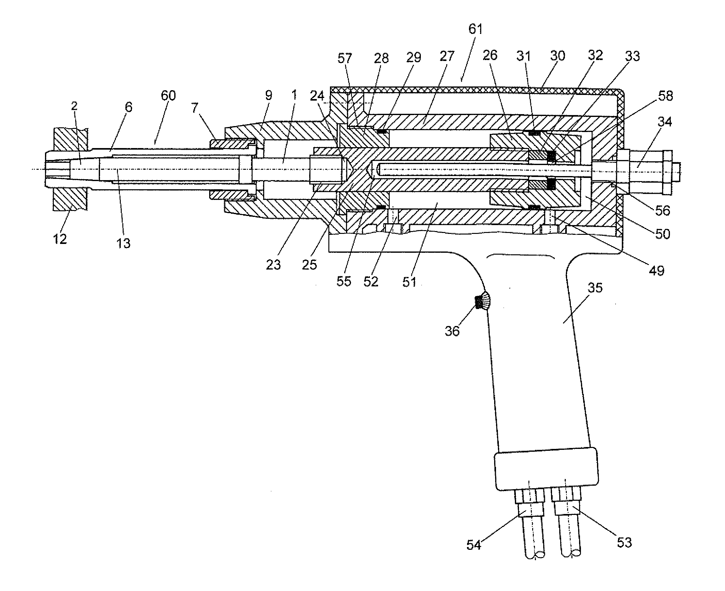
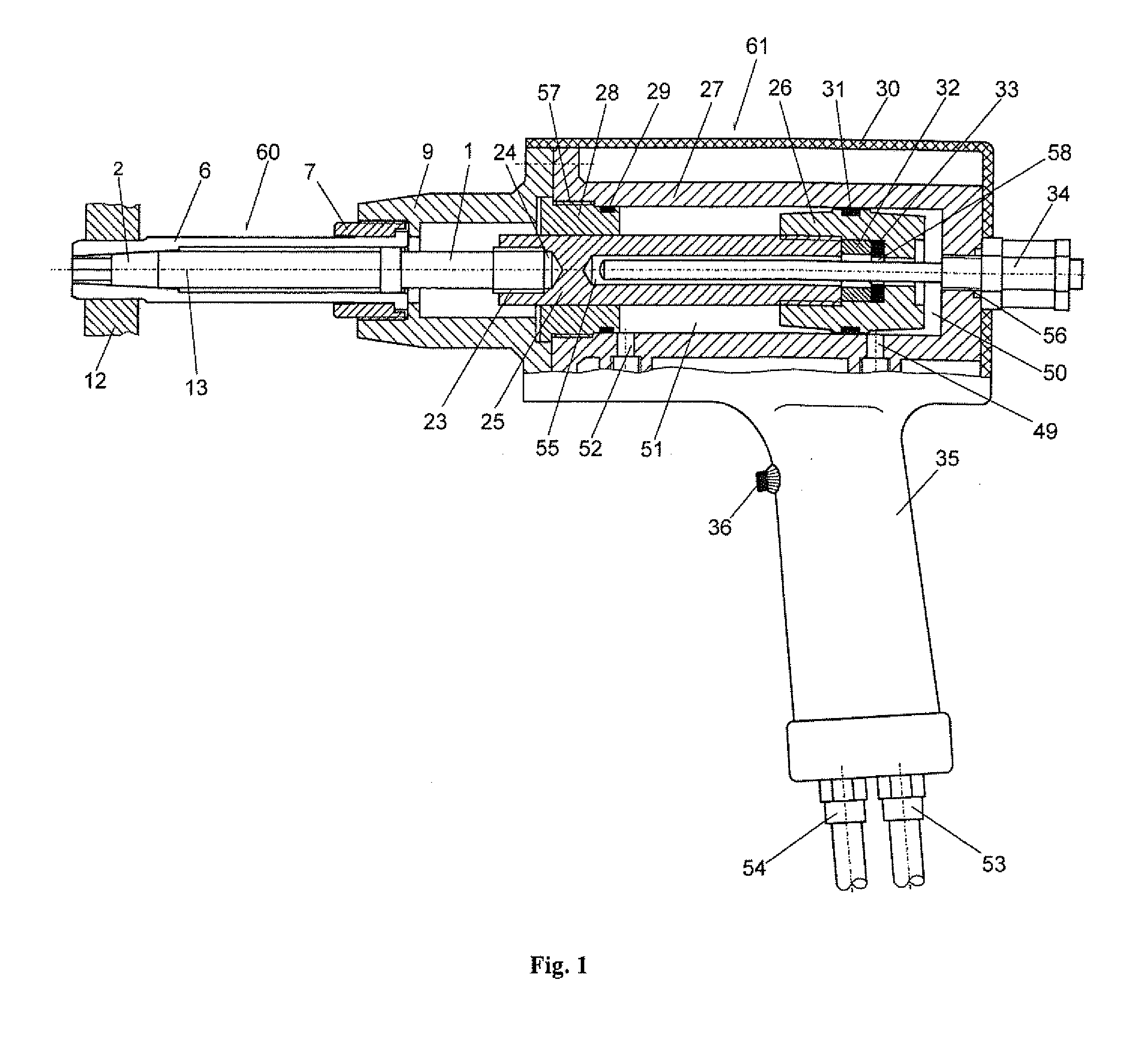
[0032]According to a preferred embodiment of the invention the device 61 for cold expansion of fastener holes comprises (FIG. 1) a hydraulic cylinder 27, in which a piston 26 is placed with a seal 31, connected to a piston rod 25, in whose hole 24 by means of thread 23 a mandrel 1 of the tool 60 is fixed. To the hydraulic cylinder 27 a flange 9 is fixed to which a threaded bush 7 of the tool 60 is fixed immovably. In an axial blind hole 55 of the piston rod 25 a linear displacement sensor 34 is positioned which by means of threaded joint 56 is fixed immovably to hydraulic cylinder 27. A control block 38 (FIG. 9) is comprised, corresponding with the linear displacement sensor 34, with the pressure sensor 37 and with electromagnets 41 and 42 of hydraulic control valve 43, which is fed with working fluid by means of a hydraulic pump 46. The hydraulic control valve 43 corresponds in sequence with two ‘throttle controllable-non-return valve’ blocks 39 and 40, depending on the direction o...


PUM

PropertyMeasurementUnit
distanceaaaaaaaaaa
distanceaaaaaaaaaa
distanceaaaaaaaaaa

Abstract

The invention refers to a device and a tool for cold expansion of fastener holes. The advantages of the device and tool are in the possibility to control the degree of cold expansion. The device (61) comprises a hydraulic cylinder (27) in which a piston (26) with a piston rod (25) is placed, to whose end a mandrel (1) of a tool (60) is fixed. To flange (9) a threaded bush (7) of the tool (60) is immovably fixed, such that in an axial blind hole (55) of the piston rod (25), a linear displacement sensor (34), is positioned, immovably fixed to the hydraulic cylinder (27). A magnet (33) is designed for activating the linear displacement sensor (34), which is connected to the control block (38).

Description

FIELD OF THE INVENTION[0001]The field of the invention relates to a device and a tool for cold expansion of fastener holes by means of plastic deformation and can be applied in working of holes in structural elements subjected subsequently to cyclic external loads, which are made of tough-plastic materials and of anisotropic aluminum / carbon fiber reinforced plastics.BACKGROUND OF THE INVENTION[0002]From U.S. Pat. No. 4,665,732 a device is known for cold expansion of holes by means of a tool comprising a longitudinally split hollow mandrel. A round pin is introduced into the axial hole of the mandrel. The device comprises a hydraulic cylinder in which a first piston with a piston rod is placed to whose end the longitudinal split hollow mandrel of the tool is fixed. A support in contact with the work piece to be worked during pulling the hollow mandrel through the hole, is fixed immovably. In an axial hole worked in the first piston and its piston rod, a second piston rod is inserted ...

Claims


Application Information

Patent Timeline
Patent Type & Authority Applications(United States)
IPC IPC(8): B29C35/16
CPCB29C67/0029B23P9/025
Inventor MAKSIMOV, YORDAN TODOROVDUNCHEVA, GALIA VELIKOVA
Owner MAKSIMOV CONSULT
Why Eureka
Try Eureka