Board inspection apparatus

a technology of inspection apparatus and board, which is applied in the direction of television systems, instruments, printed circuit manufacture, etc., can solve the problems of failure of above described failures and defective solder detection as passing, and achieve the effect of improving inspection accuracy and ensuring bonding ability with the componen

Active Publication Date: 2013-02-21
CKD
View PDF4 Cites 3 Cited by
  • Summary
  • Abstract
  • Description
  • Claims
  • Application Information

AI Technical Summary

Benefits of technology

[0032]According to the fourth embodiment of the claimed invention, not only when it is not possible to sufficiently secure bonding ability with the component because the crush amount of the solder is excessively small during m...

Problems solved by technology

However, when the solder is inspecting based on average height of the resist film, it is possible that defective solder may be determined as passing due to an inability to sufficiently ensure actual bonding ability with the electronic components despite there being a sufficient amount of solder protruding from the standard position (i.e., average height position).
In a similar manner, when inspection of this solder is performed using ...

Method used


Image

  • Board inspection apparatus
  • Board inspection apparatus
  • Board inspection apparatus

Examples


Embodiment Construction

[0043]One or more embodiments of the claimed invention are explained below while referring to figures.

[0044]As shown in FIG. 2, the printed board 1 is equipped with an electrode pattern 3 formed from copper foil on a base board 2, which is formed from glass epoxy resin or the like and has a flat plate shape (i.e., provided with a flat surface). Cream solder 4 is printed on a certain electrode pattern 3.

[0045]The printed board 1 is coated by a semi-transparent resist film 5 so that the cream solder 4 is only carried on the printed board 1 at a certain part of the wiring of the electrode pattern 3.

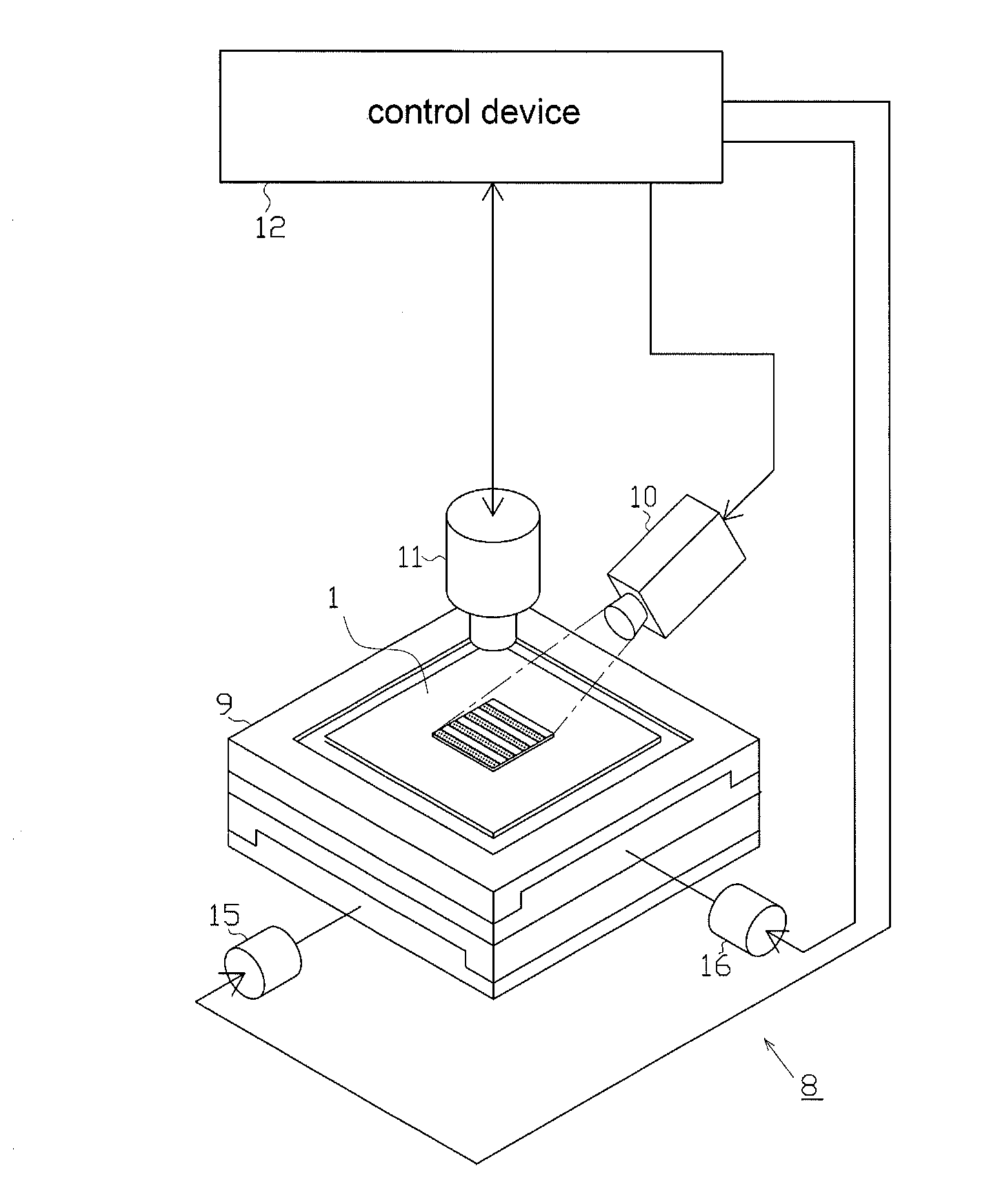
[0046]FIG. 1 is a schematic structural drawing of the board inspection apparatus 8 of the present embodiment equipped with a three-dimensional measurement apparatus. As shown in this drawing, the board inspection apparatus 8 includes: a carrying stage 9 for carrying the printed board 1, an irradiation device 10 as an irradiation unit for irradiating a certain light component pattern from abo...


PUM


Abstract

A board inspection apparatus includes an irradiation unit, an imaging unit, and an image processing unit. The image processing unit includes a three-dimensional measurement unit configured to perform three-dimensional measurement of the surfaces of the solder and the resist film by a certain three-dimensional measurement method based on the image data, a virtual standard surface setting unit configured to set a virtual standard surface corresponding to a contacting surface of a certain component mounted in a certain area of the printed board, a protrusion amount calculation unit configured to calculate a protrusion amount from the virtual standard surface for each solder printed and formed in the certain area, and a determination unit configured to determine whether the printed state of the solder passes or fails based on each of the protrusion amounts of the solder.

Description

CROSS-REFERENCE TO RELATED APPLICATIONS[0001]This application claims priority to Japanese Patent Application No. 2011-177797 filed on Aug. 16, 2011, the entire contents of which are hereby incorporated by reference.BACKGROUND OF INVENTION[0002]1. Field of the Invention[0003]The present invention relates to a board inspection apparatus for inspection of condition of solder that has been printed or the like on a printed board.[0004]2. Background Art[0005]Generally, a printed board is equipped with an electrode pattern on a base board formed from glass epoxy resin, and the surface of the printed board is protected by a resist film. When electronic components are mounted on the above mentioned printed board, firstly, cream solder is printed at certain positions on the electrode pattern that are not protected by resist film. Thereafter, the electronic components are temporarily fixed to the printed board by use of viscosity of the cream solder. The above-mentioned printed board is convey...

Claims


Application Information

Patent Timeline
IPC IPC(8): H04N7/18
CPCG01N21/95684H05K3/3484H05K3/3436G01N2021/95638H05K3/3485
Inventor ISHIGAKI, HIROYUKI
Owner CKD
Why Eureka
Try Eureka