
Two-Stroke Internal Combustion Engine

a two-stroke, internal combustion technology, applied in combustion engines, machines/engines, cylinders, etc., can solve the problems of mixing charged into the combustion chamber and yet unburned is discharged outside, deteriorating fuel consumption, and inviting an increase in unburned components, so as to reduce short-cut phenomenon, improve directivity of the second, and flow velocity. low

Active Publication Date: 2013-02-14
YAMABIKO CORP
View PDF6 Cites 2 Cited by
  • Summary
  • Abstract
  • Description
  • Claims
  • Application Information

AI Technical Summary

Benefits of technology

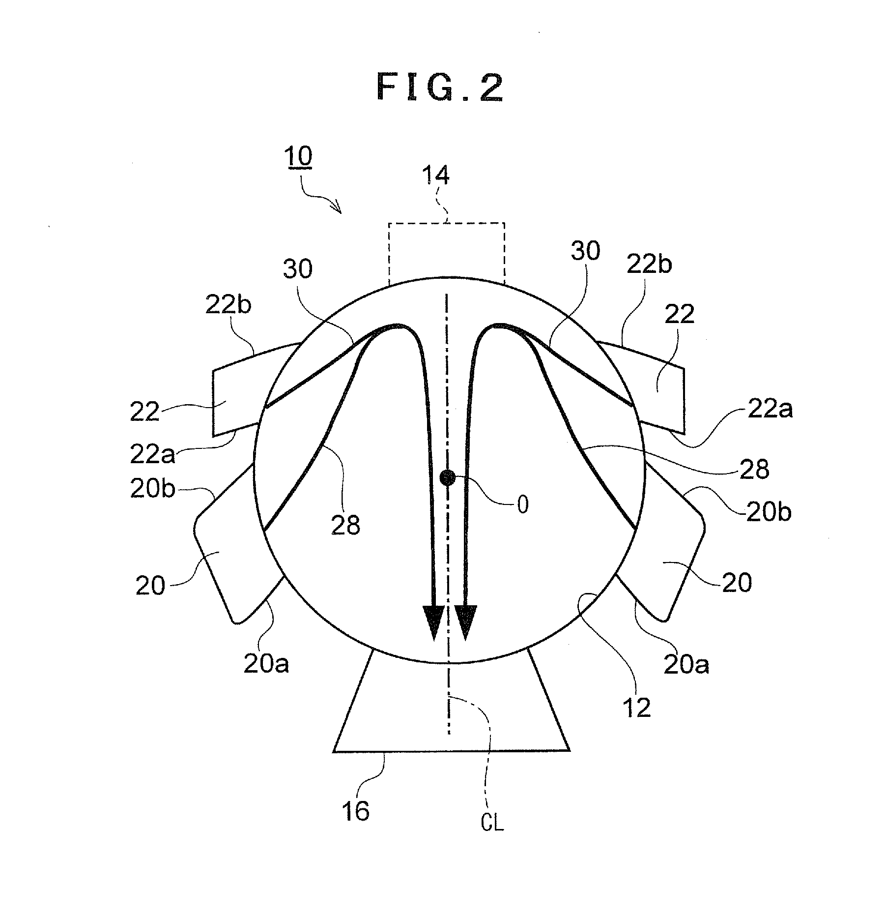
The invention provides an engine structure that prevents the phenomenon of "blow-by" during the exhaust stroke. This is achieved through a modification of a conventional engine that includes the use of a branch scavenging passage that provides higher velocity airflows to the combustion chamber, which reduces the short-cut phenomenon and improves engine performance. The first scavenging airflow is drawn towards the second scavenging airflow, which prevents the blow-by from occurring in the later half of the exhaust stroke. The second scavenging airflow can be either air-fuel mixture or fresh air, which can be supplied through the branch scavenging passage.

Problems solved by technology

Since such engines are configured to discharge exhaust gas from the combustion chamber while supplying air-fuel mixture into the combustion chamber, they involve the problem that the mixture charged into the combustion chamber and yet unburned is discharged outside.
The blow-by of air-fuel mixture not only deteriorates the fuel consumption but also invites an increase of unburned component (HC=hydrocarbon) in the exhaust gas.

Method used


Image

  • Two-Stroke Internal Combustion Engine
  • Two-Stroke Internal Combustion Engine
  • Two-Stroke Internal Combustion Engine

Examples


Embodiment Construction

[0041]Some embodiments of the invention is explained below with reference to the drawings.

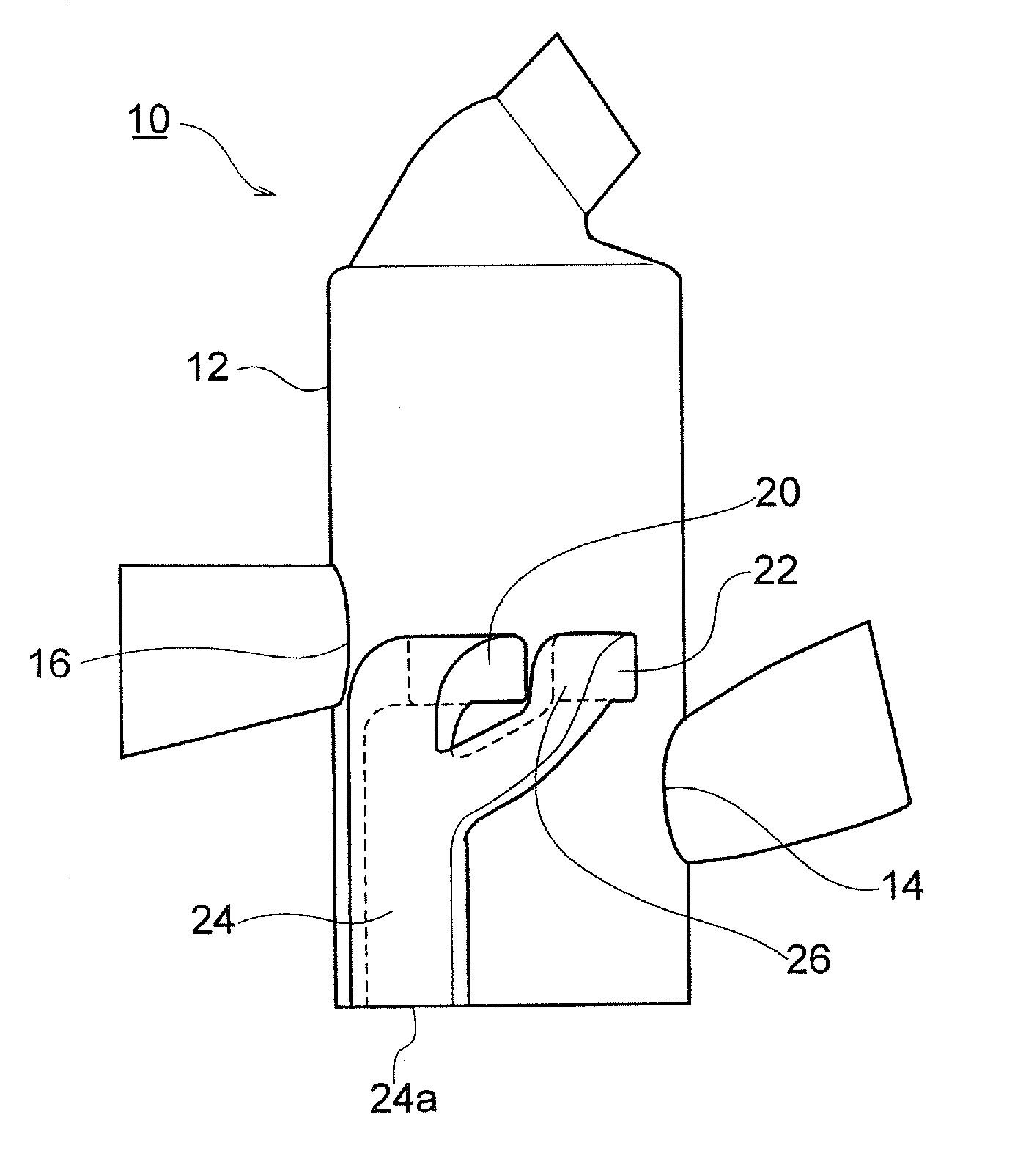
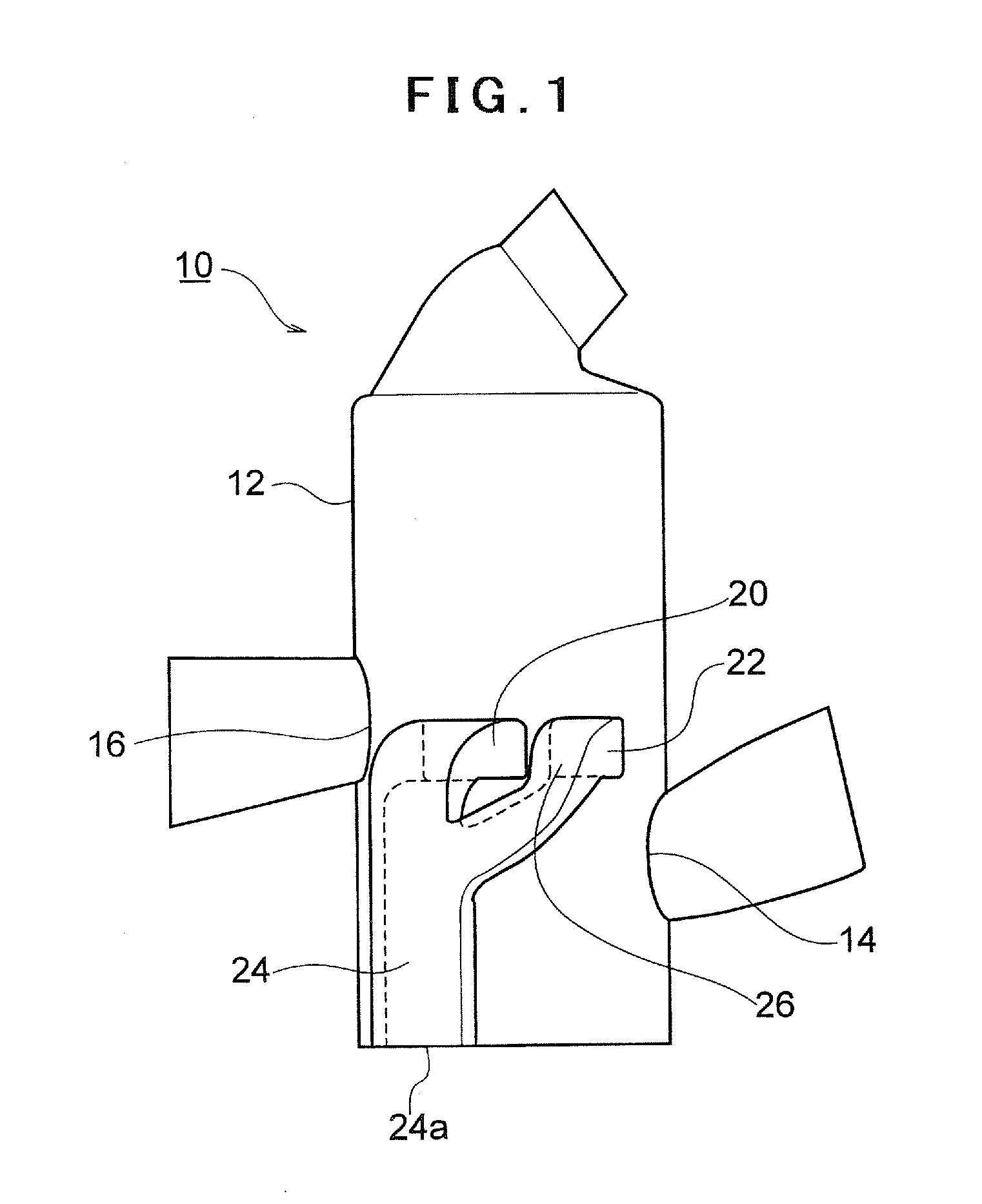
[0042]FIGS. 1 through 3 show an embodiment of the invention. As shown in FIG. 1, an air-cooled single-cylinder two-stroke internal combustion engine 10 has a cylinder bore 12 that may be, for example, an aluminum die cast product. An intake port 14 and an exhaust port 16 are formed at diametrically opposite positions of the cylinder bore 12. Air-fuel mixture introduced from the intake port 14 is charged in the crankcase (not shown).

[0043]With reference to FIG. 2, a pair of the first and second scavenging ports 20 and 22 is provided at each of axisymmetric positions about an imaginary line CL that connects the center of the cylinder bore O and the center of the exhaust port 16. The first and second scavenging ports 20 and 22 are opened and closed by strokes of piston (not shown). These features of the two-stroke internal combustion engine 10 according to the embodiment of the invention so far de...


PUM


Abstract

It is intended to effectively prevent blow-by with no need for large changes in typical structures of two-cycle internal combustion engines. A main scavenging passage (24) for supplying air-fuel mixture from a crankcase to a combustion chamber for scavenging purposes has a branch scavenging passage (26) that extends upward aslant toward an intake port (14). The main scavenging passage (24) communicates with a first scavenging port (20) located nearer to an exhaust port (16). The branch scavenging passage (26) communicates with a second scavenging port (22). A mean cross-sectional area of the branch scavenging passage (26) is smaller than that of the main scavenging passage (24). Cross-sectional area of a portion (24b) next to an inlet port (24a) of the main scavenging passage (24) opening to the crankcase is smaller than the sum of cross-sectional areas of the first and second scavenging ports (20, 22).

Description

CROSS-REFERENCE TO RELATED APPLICATIONS[0001]The present application claims priority from Japanese Patent Application No. 2011-174936, filed Aug. 10, 2011, which is incorporated herein by reference.BACKGROUND OF THE INVENTION[0002]1. Field of the Invention[0003]The present invention relates in general to a two-stroke internal combustion engine, and more specifically relates to a two-stroke internal combustion engine that is capable of reducing the blow-by of air-fuel mixture.[0004]2. Description of Related Art[0005]Two-stroke internal combustion engines, composed of only a small number of parts, are lightweight and compact. Therefore, they are conveniently used as power sources of chain saws and brush cutters. Two-stroke internal combustion engines, in general, have a structure in which a piston opens and closes exhaust ports of a cylinder in its up-and-down movements in the cylinder. Since such engines are configured to discharge exhaust gas from the combustion chamber while supply...

Claims


Application Information

Patent Timeline
Patent Type & Authority Applications(United States)
IPC IPC(8): F02B33/04
CPCF02B25/02F02B63/02F02F1/22F02B33/04
Inventor OTSUJI, TAKAMASAKOBAYASHI, BUHEI
Owner YAMABIKO CORP
Learn More