
Spark plug and method for manufacturing spark plug

a manufacturing method and spark plug technology, applied in spark plugs, machines/engines, electrical equipment, etc., can solve the problems of reducing the wall thickness of the insulator, the inability of the spark plug to maintain the voltage characteristics, and the structure of the internal combustion engine to which the spark plug is mounted, so as to prevent leakage of current in the insulator effectively, good combustible gas ignitability, and high repeatability

Active Publication Date: 2012-12-20
NGK SPARK PLUG CO LTD
View PDF0 Cites 8 Cited by
  • Summary
  • Abstract
  • Description
  • Claims
  • Application Information

AI Technical Summary

Benefits of technology

The present invention relates to a spark plug with good combustible-gas ignitability even when it is downsized. The invention solves the problem of ignitability deterioration in downsized spark plugs during high-load operation of the internal combustion engine. The solution involves a spark plug with a center electrode, an insulator, and a metal shell, where the insulator has a wall thickness of 0.3 to 1.1 mm and is formed of an alumina-based sintered body containing a Si component, a rare earth element component, and components of at least two kinds of Group 2 elements of the periodic table according to IUPAC recommendations. The ratio of rare earth element component to Si component, as well as the ratio of total mass of rare earth element component to total mass of Si component, in the alumina-based sintered body, are important factors in achieving good combustible-gas ignitability. The invention also provides a method for high-yield manufacturing of the spark plug.

Problems solved by technology

The structure of the internal combustion engine to which the spark plug is mounted has recently been becoming more complicated.
However, the spark plug cannot maintain its withstand voltage characteristics when the wall thickness of the insulator becomes decreased.
This results in a deterioration of the ignitability of the spark plug.
In each of these internal combustion engines, the ignition part of the spark plug is subjected to extreme conditions due to increases in the ambient temperature and discharge voltage of the spark plug.
When the spark plug, particularly the downsized spark plug, is subjected to such extreme conditions, the ignitability of the spark plug could significantly deteriorate during high-load operation of the internal combustion engine.
The spark plug cannot receive a required amount of energy for the spark discharge and thus cannot generate a proper spark discharge within the spark discharge gap between the center electrode and the ground electrode.
The ignitability deterioration of the spark plug directly leads to a deterioration of emission performance.

Method used


Image

  • Spark plug and method for manufacturing spark plug
  • Spark plug and method for manufacturing spark plug
  • Spark plug and method for manufacturing spark plug

Examples


examples

[0091](Production of Alumina-Based Sintered Bodies)

[0092]A raw material powder was prepared by mixing an alumina powder, a Si compound powder, any of a Ca compound powder, a Mg compound powder, a Ba compound powder and a Sr compound powder as a Group 2 element compound powder, a rare earth element compound powder and optionally a B compound powder (Sample No. 2). (The kinds of the raw powders mixed for preparation of the raw material powder are indicated in Table 1.). The average particle size of the alumina powder was 2.1 μm, whereas the average particle size of each of the Si compound powder, the Group 2 element compound powder and the rare earth element compound powder was in the above-mentioned range. The raw material powder was formed into a slurry by the addition of a hydrophilic binding agent such as polyvinyl alcohol and water as a solvent.

[0093]The slurry was subjected to spray drying, thereby granulating the raw material powder to spherical particles having an average part...


PUM

PropertyMeasurementUnit
wall thicknessaaaaaaaaaa
mass ratio RREaaaaaaaaaa

Abstract

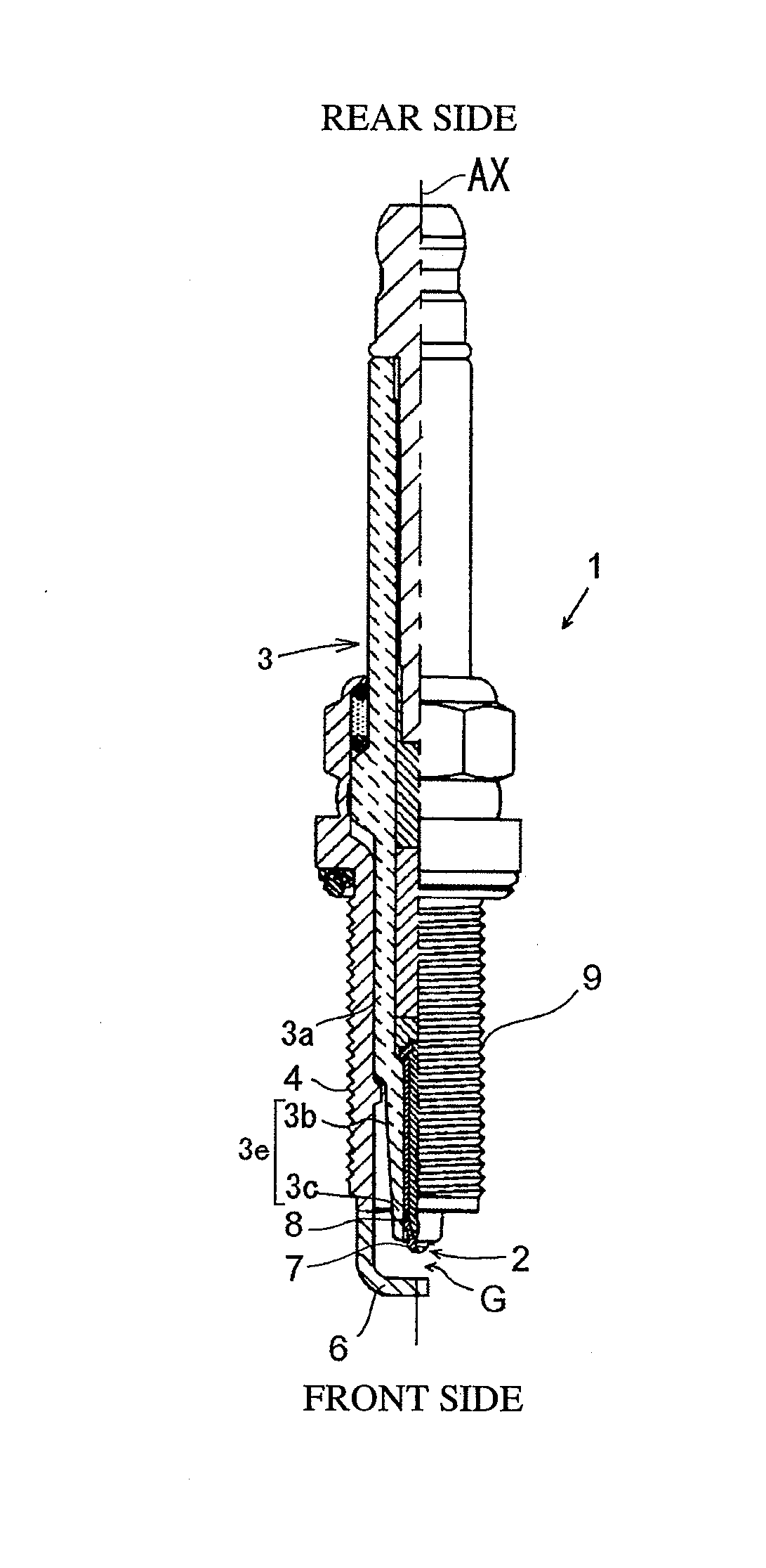
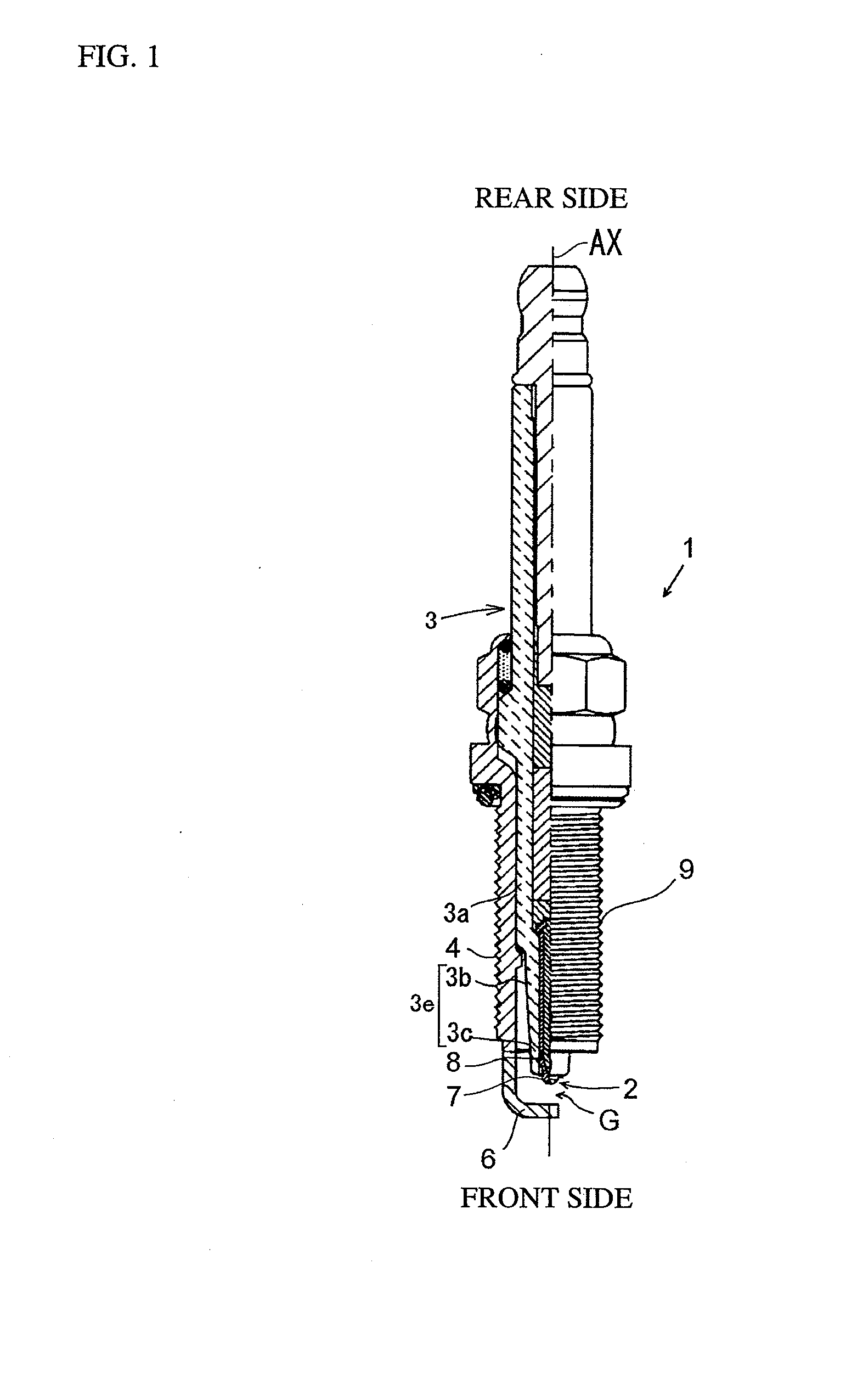
The present invention relates to a spark plug having good combustible-gas ignitability even when the spark plug is downsized and to a method for high-yield manufacturing of a spark plug with good combustible-gas ignitability. There is provided according to one aspect of the present invention a spark plug 1 having a center electrode 2, an insulator 3 and a metal shell 4 and satisfying the following conditions (1) to (5). There is provided according to another aspect of the present invention a manufacturing method of a spark plug including the step of producing an insulator by preparing a raw material powder in such a manner that the particle size distribution ratio (90% volume diameter / 10% volume diameter) between particles of 10% volume diameter and particles of 90% volume diameter in the raw material powder is 3.6 to 5.2, and then, press-forming and sintering the prepared raw material powder.Condition (1): The insulator has a wall thickness T of 0.3 to 1.1 mm at an imaginary plane including a front end face of the metal shell.Condition (2): A region of the insulator extending from a front end of the insulator to at least 2 mm rear from the imaginary plane is formed of an alumina-based sintered body containing a Si component, a rare earth element component and at least two kinds of Group 2 element components and being substantially free from a B component.Condition (3): The mass ratio RRE of a mass of the rare earth element component to a total mass of the Si component, the Group 2 element components and the rare earth element component in the alumina-based sintered body is 0.15 to 0.45.Condition (4): The mass ratio R2 of a total mass of the components of the Group 2 elements to a mass of the Si component in the alumina-based sintered body is 0.25 or greater.Condition (5): The alumina-based sintered body includes, in a grain boundary phase thereof, an aluminate crystal containing the rare earth element component.

Description

TECHNICAL FIELD[0001]The present invention relates to a spark plug and a method for manufacturing a spark plug. More particularly, the present invention relates to a spark plug having good combustible-gas ignitability even when it is downsized and a method for high-yield manufacturing of a spark plug with good combustible-gas ignitability.BACKGROUND ART[0002]A spark plug for an internal combustion engine, such as an automotive engine, generally includes a center electrode, a substantially cylindrical insulator disposed around the center electrode, a substantially cylindrical metal shell disposed around the insulator and a ground electrode attached as desired to a front end of the metal shell. One such type of spark plug is disclosed in Patent Document 1. Patent Document 1 specifically recites therein “a spark plug comprising: a shaft-shaped center electrode; a metal shell disposed on an outer circumferential surface of the center electrode; a ground electrode having one end coupled ...

Claims


Application Information

Patent Timeline
Patent Type & Authority Applications(United States)
IPC IPC(8): H01T13/38H01T21/02
CPCC04B35/117H01T21/02C04B2235/3208C04B2235/3213C04B2235/3215C04B2235/3222C04B2235/3224C04B2235/3225C04B2235/3227C04B2235/3409C04B2235/3418C04B2235/3427C04B2235/5436C04B2235/77C04B2235/85H01T13/39C04B2235/3206C04B35/111H01T13/38
Inventor SUZUKITAKAOKA, KATSUYAHONDA, TOSHITAKAKURONO, HIROKAZU
Owner NGK SPARK PLUG CO LTD
Learn More