Bolus

a ruminant animal and physiological monitoring technology, applied in the field ofbolus, can solve the problems of low sensor sensitivity and insufficient basis for determining the health condition of the animal

Inactive Publication Date: 2012-12-06
DELAVAL HLDG AB
View PDF6 Cites 11 Cited by
  • Summary
  • Abstract
  • Description
  • Claims
  • Application Information

AI Technical Summary

Benefits of technology

[0006]The object of the present invention is therefore to alleviate these problems, and thus offer high-sensitivity registration of pressure signals in a ruminant animal's reticulum.
[0008]The proposed bolus is advantageous because it combines high acoustic sensitivity with mechanical robustness and ample protection for the sensor.
[0010]According to another preferred embodiment of the invention the substantially flat surface has an overall circular shape. Namely, this renders the design well suited for being tossed around in the reticulum without injuring the animal or interfering significantly with the digestive function.
[0011]According to further preferred embodiments of the invention the sensor module includes a piezoelectric sensor, a capacitive sensor, an inductive sensor or a microelectromechanical system (MEMS) accelerometer. A piezoelectric sensor is beneficial because it has relatively high strain sensitivity, is very rugged, has an extremely high natural frequency and has an excellent linearity over a wide amplitude range. Capacitive and inductive sensors are beneficial because they are simple and cost efficient. A MEMS accelerometer is advantageous, since such a sensor can be made very small-sized and may register movements in three dimensions. Additionally, the sensor can determine static pressures as well as extremely slow pressure variations.
[0012]According to additional preferred embodiments of the invention the sensor module includes an optical transmitter-receiver pair interconnected via an optical transmission path, where the transmission properties are variable in response to any displacements of the guide means. Such a variation may be accomplished through a pivotable mirror element connected to the guide means and having a reflective surface an angle of which is variable in at least one dimension relative to at least one of an incoming light path from the optical transmitter and an outgoing light path to the optical receiver. Hence, depending on the angle of the reflective surface different amounts of light from the transmitter reaches the receiver. The optical transmission path may further include optical fibers, for instance one or more optical fibers configured to supply light energy from the optical transmitter along said incoming light path, and one or more receiving fibers configured to receive light energy via said outgoing light path and transport the received light energy to the optical receiver. The employment of optical fibers renders the design flexible in terms of where the transmitter and receiver can be located. On the other hand, transmitting the light without dedicated conduits renders the design less complex and more cost efficient.
[0014]According to still another preferred embodiment of the invention the case unit has a general cylinder shape with first and second short sides. The mechanical amplifier element is here arranged to extend from the first short side. Further preferably, the case unit likewise includes a ballast having such weight and position relative to the contents of the case unit that a center of gravity of the case unit is located closer to the second short side than the first short side. Thereby, the bolus is balanced by the ballast and the buoyancy such that the first short side with the mechanical amplifier element points in a general upward direction when the bolus is installed in the animal, and this in turn, improves the sensor's sensitivity.

Problems solved by technology

However, the body temperature alone as determined in the former reference does not provide an adequate basis for determining the animal's health condition.
Unfortunately, this also means that the sensor's sensitivity becomes comparatively low.

Method used


Image

  • Bolus
  • Bolus
  • Bolus

Examples


first embodiment

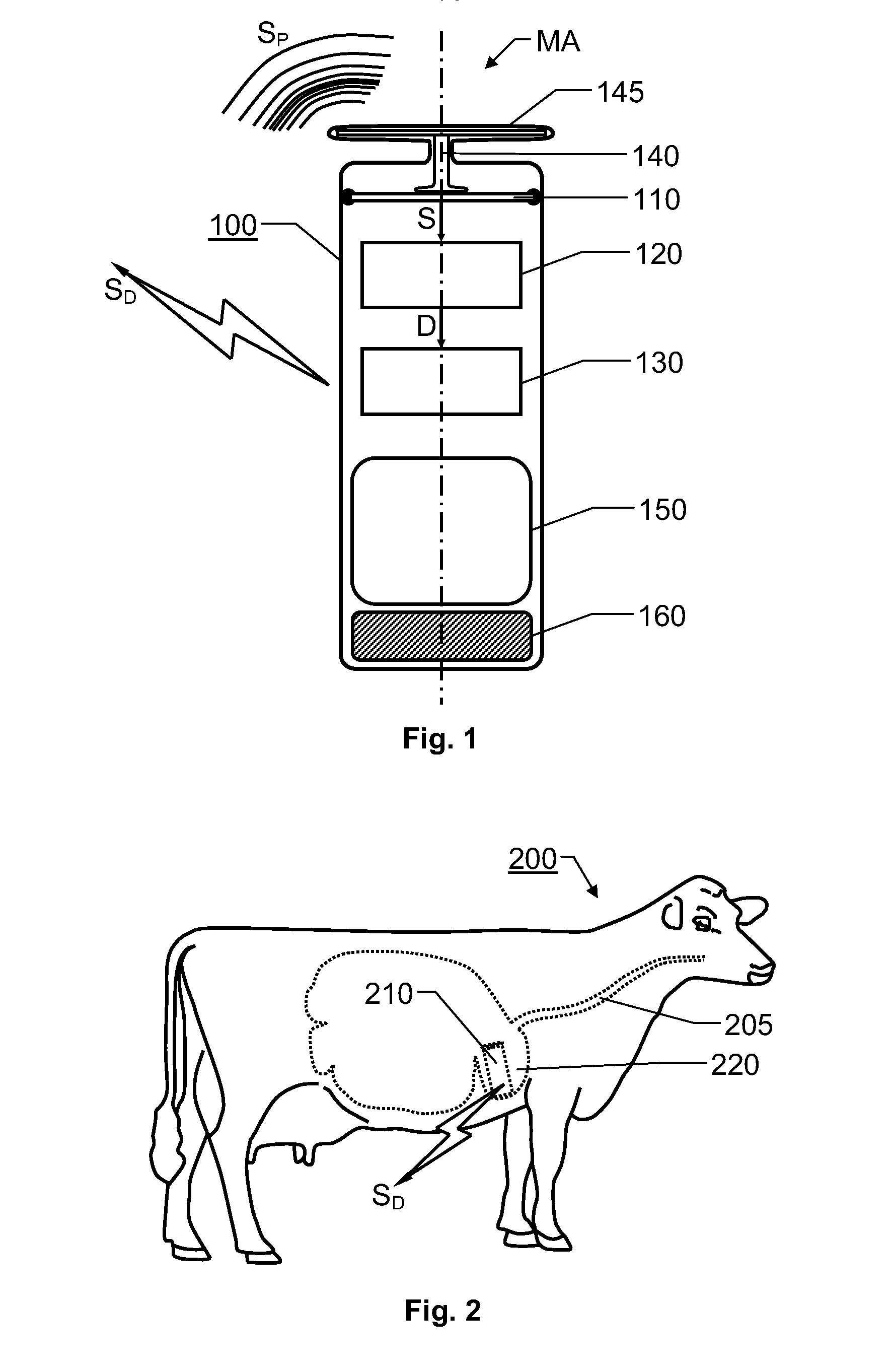
[0031]FIG. 3a shows a sensor module 110 according to the invention, wherein the sensor module 110 includes a piezoelectric sensor 111, e.g. disc shaped. As can be seen in FIG. 3a, the guide means 140 is operatively connected to the sensor 111, such that any forces exerted on the mechanical amplifier element MA can be transported to the sensor 111. A support plate 112 (preferably of metal) is arranged on the opposite side of the sensor 111 to enable deformation of the sensor 111 in response to any forces applied via the guide means 140. To limit a maximum possible force exerted on the sensor 111 the sensor 111 is preferably connected to the case unit 100 via resilient members 113, e.g. of silicon. Alternatively, the sensor 111 may be held in the interior of the case unit 100 between a fixed support structure and a wave-shaped washer, which is configured to flex in response to a predefined force. Hence, any excessive external forces exerted on the sensor 111 can be absorbed by the wav...

second embodiment

[0033]FIG. 3b shows a sensor module 110 according to the invention, wherein the sensor module 110 includes a capacitive sensor. Here, a first metal plate 114 is arranged over a second metal plate 115, and a dielectric material (e.g. air) separates the first metal plate 114 from the second metal plate 115. A detector circuit 117 is used for measuring a capacitance between the first and second metal plates 114 and 115. The detector circuit 117 may either be connected to the second metal plate 115 and a guard ring 115a arranged concentrically around the sensor metal plate 115 (as shown in FIG. 3b), or the detector circuit 117 may be connected to both the first and second metal plates 114 and 115. In any case, analogous to the above, movements of the first metal plate 114 causes variations in the capacitance, which in turn may reflect heart activities, activities of the respiratory organs and / or stomach activities.

[0034]More precisely, for a constant distance between the metal plates 11...

third embodiment

[0037]FIG. 3c shows a sensor module 110 according to the invention, wherein the sensor module 110 includes a MEMS accelerometer configured to register acceleration and deceleration parameters. This type of component is advantageous because it can be designed as a so-called 3-axis sensor capable of registering deformations in three dimensions x, y and z (i.e. downwards / upwards as well as lateral movements in a plane). A 3-axis MEMS accelerometer detects acceleration and deceleration in three independent directions. Since gravitation constitutes one important example of acceleration (namely towards earth), the sensor can detect how it is oriented relative to earth with respect to each of said axes. Consequently, in addition to the above-mentioned pressure variations, the sensor may also determine static pressures. Additionally, extremely slow pressure variations can be registered accurately.


PUM


Abstract

A bolus, for introduction into a ruminant animal's reticulum to register pressure signals transmitted through fluids therein, has a case unit adapted for immersion in the fluids. A mechanical amplifier element extends out from the case unit and is adapted to be surrounded by the fluids in the reticulum and absorb mechanical energy from the pressure signals. A guide part conveys mechanical energy from the mechanical amplifier element to a sensor module in the interior of the case unit. The sensor module transduces the pressure signals into electric signals from which a processing module extracts data representing body movements, a heart beat rate, a respiratory rate, a respiratory depth and / or stomach activity of the animal. A communication module in the case unit receives the data and transmits output radio signals reflecting the data.

Description

THE BACKGROUND OF THE INVENTION AND PRIOR ART[0001]The present invention relates generally to monitoring of the physiological status of ruminant animals, such as dairy animals. More particularly the invention relates to a bolus according to the preamble of claim 1.[0002]To accomplish an efficient and animal friendly livestock handling it is important that the animals' physiological state and health condition be monitored. Of course, to this aim, regular farmer's inspections and veterinary examinations can never be excluded. However, as a complement thereto and to provide an ongoing supervision, various automatic systems can be employed. One example of such a solution involves introducing a so-called bolus into the animal's stomach. More precisely, the bolus should preferably be placed in the reticulum, and normally the bolus has a weight of around 50-200 grams in order to not be forwarded through the digestive system. Once installed in the animal, the bolus may register internal bod...

Claims


Application Information

Patent Timeline
Patent Type & Authority Applications(United States)
IPC IPC(8): A61B5/07
CPCA01K11/007A61B5/02438A61B5/073A61B5/1107A61B2503/40A61B5/42A61B2562/0219A61B2562/0247A61B5/113
Inventor BIRK, UZI
Owner DELAVAL HLDG AB
Why Eureka
Try Eureka